


Overview
Welcome to the world of routing. In the next few chapters, we will look at how packets find their way in networks through routers. In this chapter, we will learn static routing.
Routers in our networks discover remote networks in one of two ways;
- Statically configured routes
- Dynamic routing protocols
We will learn various concepts on static routes such as how to configure static routes, how the routing table bases its decisions, routing interfaces among other concepts.
Introduction
as you may already know, the work of the router is to forward packets from the source device to the destination device. In between there may be several routers. The router uses a database known as the routing table to forward these packets.
In previous chapters, we connected a router to computer and verified communication by using ping. However, refer to the topology shown in the exhibit below.
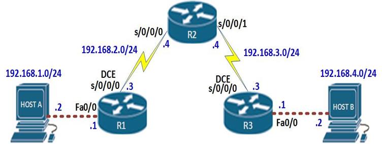
The network above shows a small network consisting of 3 routers and 2 hosts. As discussed earlier, each connection to a router should have its own network segment and this is shown in the diagram.
The network administrator also configured R1’s and R3’s serial interfaces as the DCE and all other configurations are correct.
In this scenario, R1 can ping HOST A, R1 can ping R2 s0/0/0 interface but not interface s0/0/1.
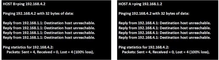
R3 can ping HOST B, R3 can ping R2’s s0/0/1 interface ONLY. HOST A and HOST B cannot communicate. As shown in the exhibit below.
In this chapter, we will explain the reasons as to why these two computers cannot communicate and resolve this problem.
KEEP THIS TOPOLOGY IN MIND AS IT WILL BE USED THROUGHOUT THIS CHAPTER.
Directly connected networks
The routing table is the database that contains information about various networks, we have said that these remote networks may either be learnt through routing protocols or manually configured routes.
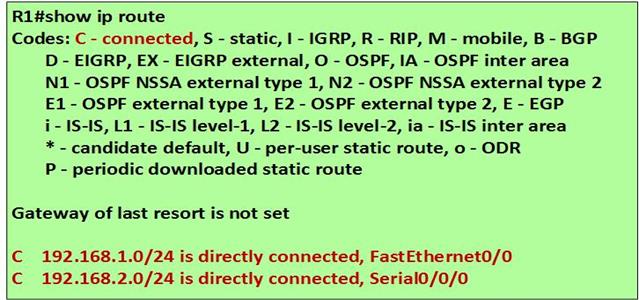
The output of the “show ip route” command on a router, shows the routes that a particular router can reach. By default, a router will only know of directly connected routes.
Directly connected routes in our scenario, from R1’s perspective are the network connected to HOST A and the network between R1 and R2.
Since no other configuration has been made on these routers, R2 and R3, should only have directly connected routes.
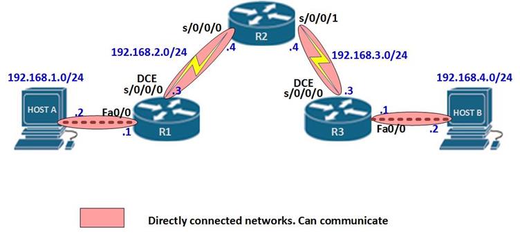
The directly connected networks are the only networks that can be reached by a particular router. In our scenario, this means that;
-
Host A can ping R1
-
R1 can ping R2’s s0/0/0 interface but not interface s0/0/1
-
R2 can ping R1’s s0/0/0 interface but not interface fa0/0 or HOST A
-
R2 can ping R3’s s0/0/0 interface but not interface fa0/0 or HOST B
-
R3 can ping R2’s s0/0/1 interface but not interface s0/0/0
-
HOST B can ping R3.
-
Neither hosts can ping each other
-
R1 and R3 cannot ping each other.
The figure shown below shows all the directly connected networks.
Static routing
Static routes are one way we can communicate to remote networks. In production networks, static routes are mainly configured when routing from a particular network to a stub network.
stub networks are networks that can only be accessed through one point or one interface.
In the above scenario, the 192.168.1.0/24 and 192.168.4.0/24 networks are stub networks. This means that for hosts in these network segments only have one way to communicate with other hosts, which is R1 and R3 for the 192.168.1.0/24 and 192.168.4.0/24 networks respectively.
Understanding stub networks is crucial in understanding static routing.
The command needed to configure a static route is shown below.
Router(config)# ip route (network-address) (subnet-mask) (next-hop ip address/ exit interface)
The table below explains the meaning of each of the parameters in the ip route command as well as an example of the command which would be used on R1 to configure a static route to R3’s LAN network (192.168.4.0/24).
| Parameter | Meaning | example |
| Ip route | State that the route being configured is a static route | Ip route |
| Network-address | The network address of the destination network. This is the network I am trying to reach. | 192.168.4.0 |
| Subnet-mask | The network address of the destination network that I am trying to reach | 255.255.255.0 |
| Next hop ip address | This is the ip address of the router that is connecting me to the desired network | 192.168.2.4 |
| Exit interface | This is the exit point interface on my router that connects to the router that will take me to the desired network | s0/0/0 |
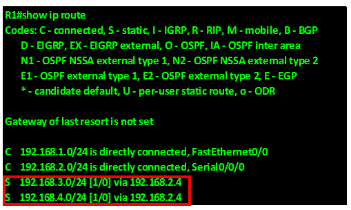
Refer to the exhibit. Therefore to configure a static route on R1 for network 192.168.4.0/24, the command to be issued on R1 is:
R1(config)# ip route 192.168.3.0 255.255.255.0 192.168.2.4
R1(config)# ip route 192.168.4.0 255.255.255.0 192.168.2.4
OR
R1(config)# ip route 192.168.3.0 255.255.255.0 s0/0/0
R1(config)# ip route 192.168.4.0 255.255.255.0 s0/0/0
NOTE: When configuring static routes
you should only use either the exit interface or the next hop ip address and not both. This will be explained later.
EXAMINE THE ROUTING TABLE ON R1:
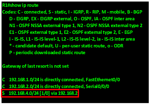
Highlighted in
red at the bottom of the show ip route output on R1, is the static route that we just added. The “S” at the beginning means that the routing table got this route as a result of a static route configuration.
In the braces, “1”, is the administrative distance for static routes, and “0” is the metric.
From this we can assume that pings from HOST A to HOST B should work. Right?
Let’s try a ping from HOST A TO HOST B and see what happens.
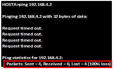
As you can see from the exhibit above, all four pings to HOST B are shown as request timed out. Further, highlighted in red
at the bottom, no packets were received by HOST B. this means that they could not communicate.
In the next section, we will explore why the two hosts could not communicate yet R1 was correctly configured with a static route.
Routing table principles
There are three routing table principles that dictate how routers communicate.
Principle 1:
“routers forward packets based on information contained in their routing tables ONLY.”
R1 has 2 routes 192.168.3.0/24 which is the connection between R2 and R3, and 192.168.4.0/24, which is the network on which HOST B is located. Therefore, based on the first principle, R1 will make its forwarding decisions based on this information only. It will not consult R2 or R3.Nor does it know whether or not those routers have routes to other networks. As a network administrator, it is your responsibility to make sure that all the routers in a network know about remote networks.
Principle 2:
” Routing information on one router does not mean that other routers in the domain have the same information.”
R1 doesn’t know about the information in R2’s routing table. The same can be said of R2 and R3. Therefore, the fact that R1 has a path to the networks connected to R2 and R3 does not mean that R2 and R3 have the same information.
For example, can reach the network 192.168.4.0/24 on R3 through R2. R1 does not know whether R2 can reach the network connected to R3. Therefore, we need to configure routes from R2 to the LAN connected to R3.
Using Principle 2, we still need to configure the proper routing on the other routers (R2 and R3) to make sure that they have routes to these three networks.
Principle 3:
“Routes on a router to a remote network do not mean that the remote router has return paths.”
This principle means that when a route is configured on one router, the remote router must be configured with a return route. In our networks, most of the communication is bidirectional, this means that for every message we send, a reply is expected.
If we use the analogy of the post office, it would be like sending a letter without a return address. The recipient cannot reply to a letter without a return address, and the postman would not know where to send the letter.
In our scenario, this means that, when we configure a route to network 192.168.4.0/24 on R1, we need to configure a route on the remote routers that leads to the LANs connected to R1.
Using Principle 3 as guidance, we will configure proper static routes on the other routers to make sure they have routes back to the 192.16.1.0/24 network.
Applying the principles:
In this scenario, we need to apply all the three principles on all the routers so that the static routes can work.
Principle 1
R1 knows how to get to network 192.168.3.0/24, and network 192.168.4.0/24, however, R2 and R3 do not know how to get there. Therefore, we need to configure a static route on R2 so that it can know how to get to 192.168.4.0/24.
Principle 2
We configured a static route on R1, however, this does not mean that R2 knows a path to 192.168.4.0/24 network. Therefore this router needs to know about that network.
Principle 3
Even though R1 and R2 have a route to network 192.168.4.0, a ping would still fail because both R2 and R3 would not know how to get to R1. Therefore, we need to configure a route that gets back to network 192.168.1.0/24 on R1.in this case we are using the next-hop ip address on both R2 and R3.
From this. We can now make the necessary configurations on all the routers to make communication between HOST A and HOST B possible.
On router R2:
R2(config)# ip route 192.168.1.0 255.255.255.0 192.168.2.3
R2(config)# ip route 192.168.4.0 255.255.255.0 192.168.3.3
On router R3:
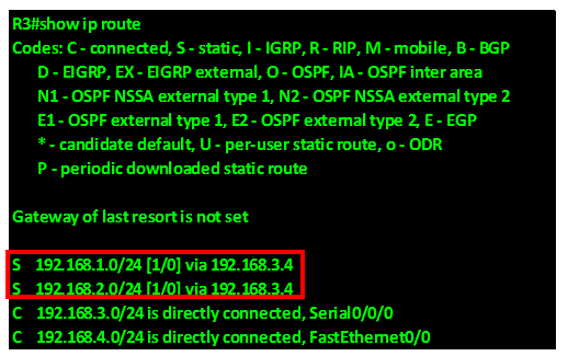
R3(config)# ip route 192.168.1.0 255.255.255.0 192.168.3.4
R3(config)# ip route 192.168.4.0 255.255.255.0 192.168.3.4
When all the configurations have been made on all the three routers, communication between HOST A and HOST B should be possible. The figure below shows the routing tables of all the three routers, the static routes have been highlighted in red.
R1:
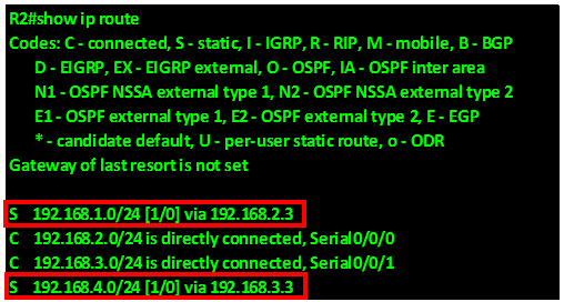
R2:
R3:
As a result of this output. We should be able to ping from HOST A to HOST B. the output below shows the results of the ping from HOST A to HOST B.
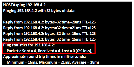
The output shows that there are replies coming from HOST B which has the ip address 192.168.4.2, the highlighted section in red shows that 4 packets were sent and all 4 were received by HOST B, with 0% loss.
Therefore, we have successfully configured static routing on the routers.
Resolving the next- hop ip address
Suppose we configured R2 with the next-hop ip address not an exit interface, how would the router know which interface to send the packets through?
Refer to the output of the show ip route command on R2, below.
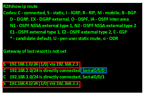
When the router wants to send a packet to the 192.168.1.0 network, it will look at the routing table.
There is a route to that network via 192.168.2.3. Then the router checks to see whether it has an interface that to the 192.168.2.3 network. In this scenario, that would be the network highlighted in blue. The exit interface is serial 0/0/0.
Routes that only have the next-hop ip address and no exit interfaces, must have resolve the next hop ip address using a route on their routing table that connects to the remote network.
In most cases, the route that the next hop is resolved to is usually a directly connected network.
As such, this is usually an issue, since the router has to process a packet twice before it can determine where to forward it. This is known as a recursive lookup.
It is recommended that static routes have an exit interface as opposed to the next hop ip address.
Summary and default routes
Suppose a router has more than 1 LAN connected to it. It would be more practical to use an address that covers all the LANS, and configure 1 static route. Take this scenario, R1 has 5 LANs connected to it;
-
192.168.1.0/24
-
192.168.2.0/24
-
192.168.3.0/24
-
192.168.4.0/24
-
192.168.5.0/24
Summarizing these routes is shown in the table below.
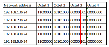
The first 2 octets and the first 5 bits from the left, in the third octet.
Therefore the new summary network address and subnet mask for the 5 networks will be: 192.168.0.0/21 with the subnet mask as 255.255.248.0.
When configuring a static route to the summary network out serial0/0/0 on R2, the command would be;
R2(config)# ip route 192.168.0.0 255.255.248.0 s0/0/0
Refer to the exhibit shown below. Suppose HOST A wants to send an email to a friend or wants to view a website on the internet, how would the router know where to send the packets?
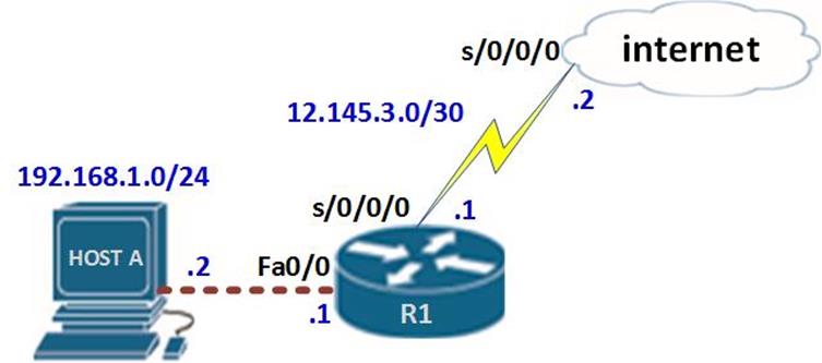
The internet has many ip addresses, and configuring one static route to a specific network would not work. Therefore, a default route is needed.
A default static route is a route that will match all packets. Default static routes are used:
When no other routes in the routing table match the packet’s destination IP address. In other words, when a more specific match does not exist. A common use is when connecting a company’s edge router to the ISP network.
When a router has only one other router to which it is connected. This condition is known as a stub router.
The syntax for configuring a static default route is:
Router(config)# ip route 0.0.0.0 0.0.0.0 [next-hop ip address/ exit interface]
A route to this network would tell the router to forward any packet for which it does not have a route to the indicated next-hop ip address or exit interface.
In this scenario, to configure a default static route, the command sequence on R1 would be.
R1(config)# ip route 0.0.0.0 0.0.0.0 12.145.3.2
Or
R1(config)# ip route 0.0.0.0 0.0.0.0 s0/0/0
Summary
In this chapter, we have learnt how a router finds a path to a remote network, we have configured static routes using the principles of the routing table, learnt about the recursive lookup, as well as configured summary routes and default static routes.
In the next chapter, we will get into the world of dynamic routing protocols.