


Overview
In part 1 and 2 of this chapter, we focused on 802.1D STP, in this chapter, we continue with STP but we will focus on the different variations of STP mainly; PVSTP and RSTP. We will begin with the concepts that make these protocols different from 802.1D STP, then we will configure PVSTP and finally look at troubleshooting and verification of STP.
PVSTP+ (Per-VLAN STP)
The development of PVSTP was a major improvement of the conventional 802.1D STP, PVST is a CISCO proprietary variant of STP that allows STP to be run per VLAN in the network. With this implementation of STP, we can have different root bridges, and port roles on the switches in the network depending on the VLAN. This also allows for load sharing.
In PVST+, you can configure different switches to be the root bridge as shown in the diagram below. Switch AS1 is the root bridge for VLAN 10 and 100 and 99. Switch AS2 is the root bridge for VLAN 20 and switch AS3 is the root bridge for VLAN 30.
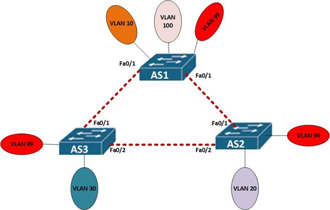
In this topology, each switch is a root bridge for its local VLANs, this means, AS1 is the root bridge for the VLANs connected to it, and so is AS2 and AS3.
VLAN 99 is a special VLAN and it is the management VLAN, it is on each switch. For this VLAN, we have configured AS1 as the root bridge.
To configure PVSTP, the steps that are taken are shown below.
Step 1. For each of the VLANs, choose the switches that will be the root bridge and the secondary root bridge respectively. Ideally, these should be the switches that have been configured with the VLANs you want to assign them to.
Step 2. For each of the VLANs, configure the switch that was chosen as the root bridge.
Step 3. The secondary root bridge for each of the VLANs should then be configured.
The modified topology below, will be our lab for PVSTP.
Topology
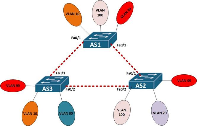
In this scenario, AS1 will be the primary root bridge for VLAN 10, and VLAN 99, it will be the root secondary for VLAN 100.
- AS2 will be the root bridge for VLAN 20 and 100 and the secondary for VLAN 99.
- AS3 will be the primary root bridge for VLAN 30 and the secondary for VLAN 10.
To configure the topology above, we use the following commands.

in our scenario, we will use the root primary and root secondary command.
NOTE: when using the priority command, the lower the priority the better and the priority value is always a multiple of 4096, e.g 4096, 8192, 16384.
To configure PVST in our scenario, the commands used are shown in the table below.
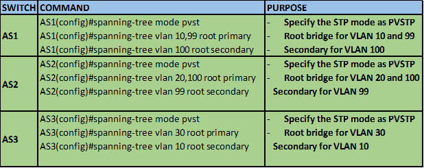
This is the configuration needed on the switches for PVSTP to be enabled.
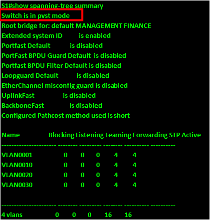
We can use the command “show spanning-tree summary” to verify that the mode of STP in use is PVSTP. As you can see from the output below, the mode of STP is shown as PVSTP, 802.1D is shown as IEEE STP.
RSTP (Rapid STP)
RSTP is an open standard enhancement of the first STP standard which was 802.1D, it is also known as IEEE 802.1W. Most of the options in RSTP are unchanged from those in 802.1D. However, it is much faster. In this section, we discuss RSTP and discover how it differs from the conventional 802.1D implementation of STP.
The main advantage that RSTP offers is the speed by which it recalculates the Spanning tree when there is a topological change. When properly configured, it is usually faster than STP and convergence is usually faster. In RSTP, we have different port states and roles. There is introduction of the alternate paths which speeds up the convergence after failure since this port immediately transitions to forwarding without the STA recalculation. Some of the RSTP characteristics are discussed below.
Since RSTP is an open standard, and it offers better speeds than 802.1D, it is the most commonly used form of STP. RSTP does not need any additional configuration on switches and in most new model switches, it is on by default.
The enhancements made in CISCO’s variant of STP such as the BackboneFast and the UplinkFast are not compatible with RSTP.
RSTP is faster than 802.1D STP and it maintains backward compatibility with this protocol.
RSTP can transition switch ports into the forwarding state without necessarily relying on timers that have been configured.
Link Types
In RSTP, we have several port roles as discussed below. On each links, the state of the port is determined by the state of the link. In RSTP, we have the edge ports and the non-edge ports. The types of links are point-to-point and shared.
- Edge ports in STP are similar to the portfast ports we had for CISCO. These ports will automatically transition to forwarding state.
- Root ports are not determined by the link type. These ports can transition rapidly to forwarding state.
- Alternate ports and the backup ports do not use the link type. These are the equivalent of the blocked or non-designated ports in STP.
- The designated ports use the link type to determine whether they will transition to the forwarding state. The designated ports that will transition to forwarding state are only those on point-to-point links.
In RSTP, the role of the port is not the same as the state of a port. For example, we can have a designated port role that is in the discarding state. In the table below, the three RSTP port states have been described.
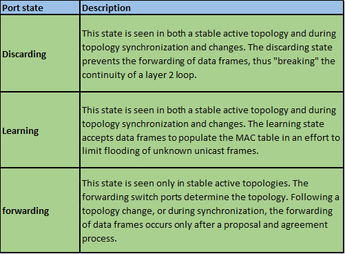
The table below shows the difference between the STP and RSTP port states.
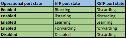
NOTE: that the STP and RSTP port roles are very key concepts and they are often asked in the CCNA certification exams.
Verification and Troubleshooting of STP
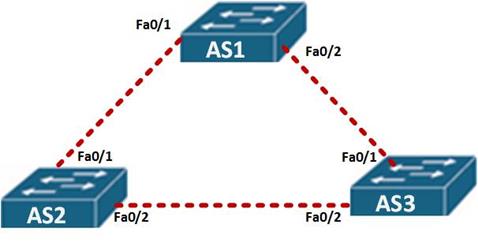
In this section, we will review some of the STP and PVSTP troubleshooting commands using the scenario shown below.
In this scenario, we are supposed to determine the root bridge for the VLANs on the three switches, using various show commands.
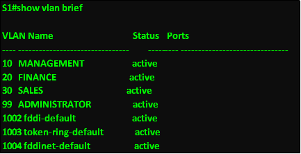
The first command we use is the show VLAN brief, so that we can identify the VLANs that are active on the switches. And based on the output below, there are 4 configured VLANs which are; 10, 20, 30, and 99 on all switches.
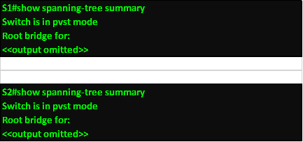
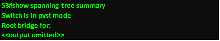
The next step is identifying the spanning tree mode that is in operation on the switches using the command show spanning-tree summary, and as you can see from the output below, all the switches are operating in PVST mode.
From this we can determine that different switches will be the root bridges for different VLANs, we can use the command

When we execute this command on S1, the output will be as shown below.
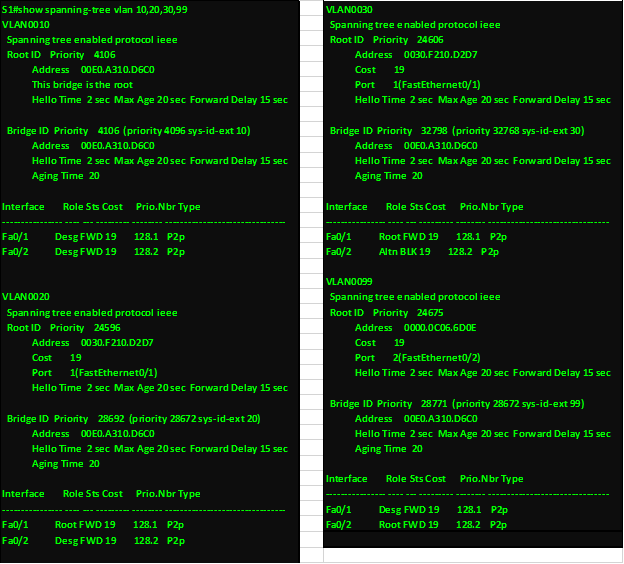
Based on the output above, S1 is the root bridge for VLAN 10 only, as shown by the identical bridge ID and root ID mac address. As well as two designated ports for this VLAN.
ALSO NOTE THAT THE PORTS ON THIS SWITCH ARE ALL IN THE FORWARING STATE.
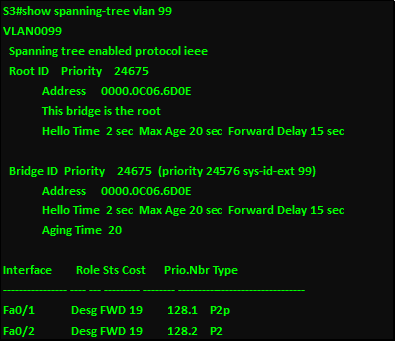
When this command is executed on S2 and S3, we should be able to see the root bridge for the other VLANs as shown in the output below for s2 and S3 respectively.
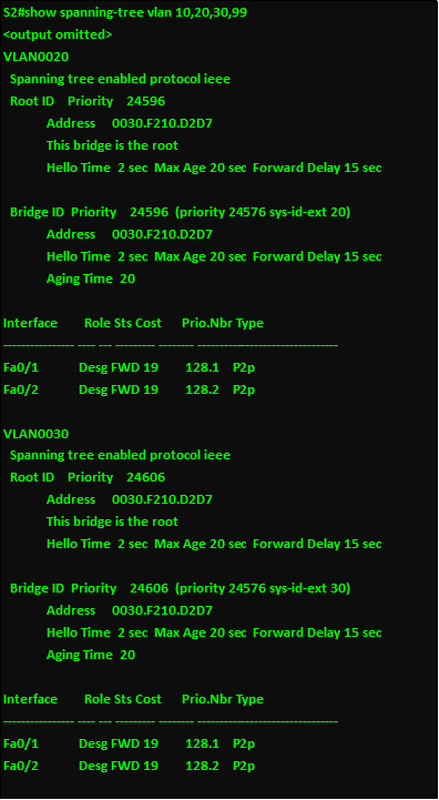
Based on the output above, S2 is the root bridge for VLAN 20 and 30 respectively, and in the figure below, S3 is the root bridge for VLAN 99.
The troubleshooting and verification commands we have learnt above are very important and can help you figure out STP issues. These concepts are usually examined thoroughly in the CCNA certification exams.
Summary
In this chapter, we have looked at the various concepts that help make our networks redundant while avoiding loops. We looked at 802.1D in part 1 of this chapter as well as concepts that make STP work. We then looked at more advanced concepts in STP including PVSTP and 802.1W which is RSTP. In the next chapter, we will look at how we can use bandwidth on our switches more effectively using ether channel.