


Overview
In part 1 and part 2 of this chapter, we looked at the basic configuration of OSPF and further learnt more OSPF concepts such as redistributing the static routes and the metric, in part three, we looked at multi-area OSPF. In part four, we will look at OSPF and multi-access networks, we will conclude with a more complex OSPF lab which will be vital not only in the ICND 1, ICND 2 and CCNA composite exams but also in real world scenarios.
Multi-access networks
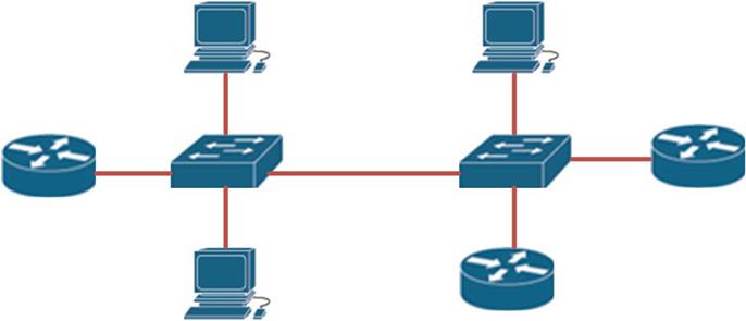
Multi-access networks, are networks that consist of more than 2 devices sharing the same media. In the example shown below, the three routers and three PCs are interconnected using the two switches at the center of the topology. This means that the interfaces on the routers that connect to the switches as well as the PCs are in the same subnet.
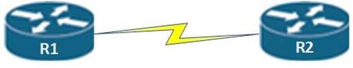
On the other hand, in Point-to-point networks, there are only two devices on one subnet. The figure shown below shows two routers which are interconnected using a WAN link. This is an example of a point-to-point network.
In OSPF, we can have 5 network types which are:
- Point-to-point
- Point-to-multipoint
- Broadcast Multiaccess
- Virtual links
- Nonbroadcast Multiaccess (NBMA)
In the CCNA course we focus on the OSPF point-to-point networks and broadcast multi-access networks. The other network types are discussed in more advanced courses such as CCNP and CCIE.
Challenges in OSPF Broadcast multi-access networks
In broadcast multi-access networks, we are faced by two challenges in an OSPF environment.
- Multiple adjacencies
- Flooding of LSAs
Multiple Adjacencies
As we discussed earlier, neighboring routers in OSPF usually create adjacencies with each other. In broadcast multi-access networks, this is a major issue.
Consider the network topology shown below. In point-to-point networks, we were used to neighbors being directly connected routers, in the example shown below, the four routers are all directly connected because they are in the same subnet.
This means that the routers in this example would flood LSAs between each other and create adjacencies with one another.
To get how many adjacencies would be created, the formula shown below can be used:
n (n-1)/2 where n Is the number of routers.
In the scenario below, we have 4 routers, using this formula:
n(n-1)/2 we get: 4(4-1)/2 = 6
This is shown in the scenario below and the adjacencies are highlighted by the blue arrows.
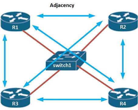
The number of adjacencies in this scenario are few, but can you imagine a large network such as one with 100 routers. This can be problematic and a big burden on the routers’ resources.
Flooding of LSAs
As we have learnt previously, OSPF uses triggered updates which are flooded to all concerned routers. Take the scenario above, if R1 lost a route to its LAN interface, this information would be broadcast to R2, R3 and R4, these routers would in turn flood that information to every router in the network except where the information originated from causing a routing loop. This is demonstrated in the figure below.
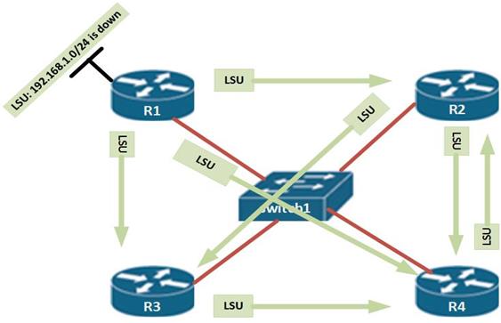
The green arrow shows the network that is down on R1. As you can see this information is propagated to R2, R3, and R4 several times which can cause a routing loop.
Solutions to OSPF broadcast multi-access problems
In OSPF, these challenges are solved by electing the DR (designated Router and the BDR (Backup Designated Router).
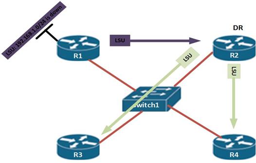
In the first instance, we saw that when a network on R1 went down, all the routers were flooded with updates about this missing route. However, with the election of the DR as shown above, R1 only informs the DR router – R2, about the missing route. The DR then updates the other routers in the multi-access network.
NOTE: in our scenario above, we have not included the BDR, however the BDR is also informed of the missing route, but it does not update other routers unless the DR is down in which case it is elevated to the role of the DR.
The election of the DR and the BDR in OSPF is a very important factor and it stops the problems we have seen. When the DR and BDR are elected, all other routers in the multi-access network become DROther, this means that they are neither the DR nor the BDR. The DROther routers will never update other routers in the network.
Election of DR and BDR
How do the DR and BDR get elected? The following criteria is applied:
- First. elect the router with the router that has the highest OSPF priority as the DR
- Second. Elect the router with the second highest OSPF priority as the BDR
- Third. If the priorities are equal, the DR is elected based on the highest router ID.
In the previous section, we discussed that the router ID is selected based on the following criteria.
- Router ID as configured using the router-id command
- Highest loopback interface
- Highest active interface in the OSPF domain.
Based on the information above, we can determine the DR and the BDR in the topology below.
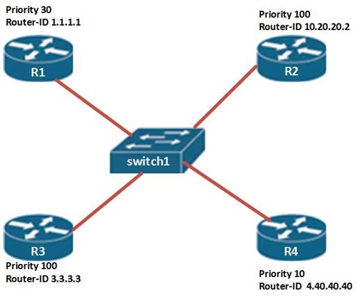
Based on the topology above, two routers are candidates for the DR, R2 and R3 this is because they have the highest router priority in the network. However, R2 has a higher router ID and therefore it will become the DR, R3 will become the BDR and will be used ONLY if R2 fails.
Promoting the BDR to the DR
The DR never changes unless one of the following happens:
- The DR fails.
- The interface connected to the multi-access network on the DR goes down.
- The OSPF process on the DR goes down.
If one of these situation happens, the BDR router is automatically elevated to the role of the DR. the routers then conduct an election to determine the new BDR. If the previously failed DR comes back online, it does not resume its role as the DR, rather, it assumes the role of a DROther.
Router priority
In most cases we would like the DR router to be selected through preference. In this case, relying on the router-ID may not be enough. The router priority in OSPF, is used to determine which router becomes the DR and the BDR in the Ethernet section as mentioned earlier.
Changing the router’s OSPF priority is key in ensuring that the right router is chosen as the DR.
To configure the router’s priority, we use the command “ip ospf priority <0- 255>” in the interface of a router which is participating in OSPF.
NOTE: A priority of 0 means that the specified router will never be the DR.
Now that we know of the concepts in OSPF and multi-access networks, we will now do a lab on these concepts and get to see how they work.
OSPF Topology
The figure shown below shows the topology we will be configuring. As you can see we have 6 routers which are all connected to 1 switch. They are all in 1 Ethernet segment in the 192.168.1.0/24 network.
Each router in this topology is using an ip address that corresponds to its router number.
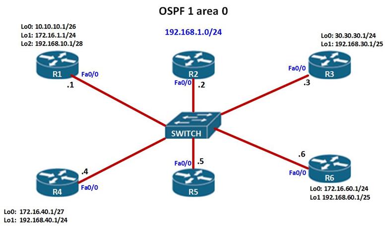
In this scenario, we are supposed to configure OSPF on all the routers and at the end of the chapter, we should be able to determine which routers will be elected as the DR and the BDR.
R1, R3, R4 and R6 all have loopback interfaces with the ip addresses shown in the diagram.
NOTE: after configuring the fast Ethernet interfaces that connect to the switch leave them in shutdown mode.
The router ID’s and ospf priorities in use are shown in the table below.
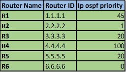
In our scenario, the basic configuration of the router has been done; our task is to configure OSPF and to determine who will be elected the DR and the BDR.
Configure OSPF
The first thing we need to configure in this scenario is OSPF on all routers. This means using the network command.
In our case we are using OSPF process id of 1 and area 0.
The table below shows the OSPF configuration statements on each of the 6 routers.
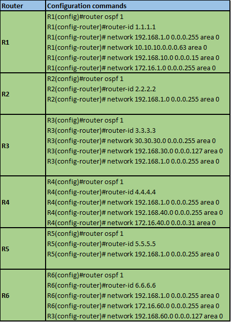
As you can see from above, all the network statements have been configured, but no routes will be advertised since the interfaces connecting the routers to the switch are in shutdown mode.
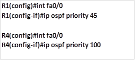
Configure OSFP priorities
The next step is to configure the OSPF priorities, this is done in the specific interface that is connected to the multi-access device using the command:

In our scenario, all routers have the same interface that is connecting to the switch which is FastEthernet 0/0.
Therefore, in each of these interfaces we will configure the OSPF priority as shown above:
The configuration of R1 and R4 is shown below.
After configuring the OSPF priority on all the routers, enable the interfaces which connect to the switch by entering the “no shutdown command”, this should enable OSPF to learn of the routes in the network.
The output of the “show ip route” command on R1 is shown below.
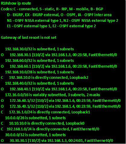
As you can see, R1 has learnt of all the routes from the neighbors.
To confirm which router is acting as the DR, we use the “show ip ospf neighbor” command on each of the routers. The output of this command on R4 is shown below.
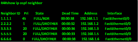
As you can see from the output, R4 has formed full neighbor relationships with all the routers in the network, further, since neighbor 1.1.1.1 is marked as the BDR and all the other routers as DROTHER, this router is the DR for this network.
The output of the “show
ip ospf neighbor” on R3 should show who the DR router is.
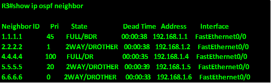
NOTE: neighbor 4.4.4.4 is in the state of “FULL/DR” and neighbor 1.1.1.1 is in the state of “FULL/BDR”, the other routers are listed in the state of “2WAY/DROTHER”.
On a multi-access network such as the one we have, the routers in the network will only form a FULL neighbor relationship with the DR and BDR. DROTHER routers only form a 2WAY relationship. The OSPF neighbor states are discussed in more details in CCNP level.
Re-election of DR and BDR
Now we are going to try and see what would happen if the DR and BDR routers are offline and not functioning.
- DR goes down
As we mentioned earlier, if the DR goes down, the BDR automatically becomes the new DR. we can test this by shutting down the FastEthernet0/0 interface on R4 which is the DR.
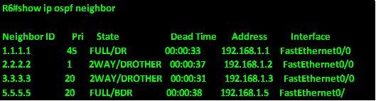
As you can see from R6’s output of the “show ip ospf neighbor” command above, neighbor 1.1.1.1 becomes the new DR, and it was previously the BDR in the network.
The election of the BDR is between neighbor 3.3.3.3 and neighbor 5.5.5.5 both of which have the same OSPF priority. Neighbor 5.5.5.5 is elected the new BDR since it has a higher router-ID.
- What if the DR comes back online?
When we enable R4’s interface by entering the “no shutdown” command on interface FastEthernet0/0, will it resume its responsibility as the DR? The output of the “show ip ospf” neighbor command on R6 could reveal the answer.
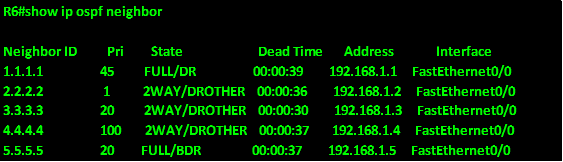
As you can see from the output above, R1 will still remain the DR while R4, even though it has a higher priority will still remain the BDR. This is a protection feature in case the router fails again.
NOTE: when a DR fails, it can only resume its role as the DR ONLY if the new DR and the new BDR fail. Even if it has the highest priority.
NOTE: a router with a priority of 0 will never become a DR or BDR in a multi-access network. More on this will be discussed in CCNP level, however, you are expected to know how the DR and the BDR are elected for your ICND 1, ICND 2 and CCNA composite exams.
Summary
OSPF in broadcast multi-access networks ends our topic on OSPF and routing. It is important to know that OSPF is one of the most important topics in not only the CCNA course but also in other levels such as CCNP. In the ICND 1, ICND 2 and CCNA composite exams, you will be examined on many OSPF concepts and your overall pass mark will depend on your understanding of these concepts. The routing world is large and cannot be covered in its entirety in the CCNA syllabus, in more advanced levels you will explore routing further, however, we have covered all the necessary routing topics in this course. In the next few chapters, we will explore switching and merge these concepts with the routing concepts.