


Overview
In this chapter, we will learn how to configure the various internetwork devices such as the router and the switch. We will also cable the network correctly according to the requirements and learn the various CISCO IOS – CISCO internetwork operating system basics that we will use throughout the course. As we mentioned in the beginning of the course, this will be a lab oriented course and therefore, you are expected to have lab equipment. If you do not have the physical devices, do not worry because we will discuss an alternative that can be used for learning purposes in this course.
Upon completion of this chapter, you will be able to:
-
Understand the role of the CISCO IOS
-
understand the config file on routers and switches
-
Understand the IOS command structure
-
Configure basic configuration of a router or a switch
-
Verify the configuration on a router using show commands.
Internetwork operating system
I am sure that you already know that computers have operating systems. The operating system allows the computer to function and also allows us to input and receive output. The operating system is the intermediary between us and the computer’s internal components. Similarly, the router also has an operating system.
CISCO uses the IOS (internetwork operating system) to allow us to use the various capabilities in the routers.
The CISCO IOS allows us to perform functions such as:
-
Routing
-
Security for the network
-
Expand the network based on requirements among others.
Unlike other operating systems that you may be accustomed to however, the CISCO IOS is accessed using a CLI (Command Line Interface). If you have used programs such as DOS™ then you are familiar with the CLI prompt.
Access methods
The CLI on routers may be accessed using one of the following ways:
-
Console port
-
Auxiliary port
-
Virtual terminal lines.
There are several programs that we can use to access the CLI on routers.
-
The console port is the main port that is used to configure a router. When the router is new and out of the box, this is the interface that is used to configure the router. After the initial configuration, we can use other configuration methods. The console port is also used for disaster recovery in case the router is unusable or as a way to troubleshoot the router when other connectivity means are unavailable.
-
The second way we can configure a router is using an auxiliary port. The auxiliary port is used to configure the router through the use of a modem. This port is rarely used and as such we will not discuss its use further.
-
The third way we can configure a router is by using the virtual terminal lines. As the name suggests, the virtual terminal lines are configured as a way to access the router remotely.
The administrator can configure the router to be accessed from a remote location using these lines.
In this course, we will learn how to configure the two types of VTY lines, either through telnet or the more secure SSL.
NOTE: the operation of the router depends on the commands that we issue during configuration as well as the IOS functioning.
Configuration files on the router
As mentioned earlier, the router is a computer and it the configuration we do determines its operation. The router has two types of memory; volatile and non-volatile memory. The configuration we make is stored in one of these two types of memory depending on the commands we issue.
There are two types of configuration files on the router.
The startup configuration file (startup-config) – this is the file that is used during the startup of the router. It is stored in the non-volatile memory which is called the NVRAM. The startup configuration consists of all the commands we have issued and saved in the router. Once the router boots up, this file is loaded from the NVRAM to the RAM where it is used as the running configuration file.
The running configuration the operation of the router is determined by the running configuration. Any command that we issue on a router is immediately executed and stored in the running- configuration. This file is stored in the RAM or the volatile memory. This means that if the router loses power, any unsaved changes in this file will be lost. When the running- configuration is saved, it is stored in the NVRAM and becomes the startup-config.
CISCO IOS modes
The CISCO CLI is structured hierarchically. The modes are executed from the top to bottom. Each mode gives access to certain commands that can be issued. The list below shows the CISCO IOS modes from the top to bottom.
-
User exec mode
-
Privileged exec mode
-
Global config mode
-
Other specific configuration modes
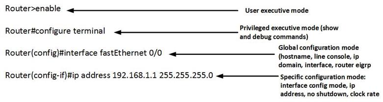
On gaining access to the router, there will be various prompts that will denote the specific level in which the administrator is in. however, the beginning of the prompt will be the router’s name. The various prompts are discussed below.
-
User executive mode
This is the main or the first mode that one can access on a router. It is limited to few verification and troubleshooting commands. By default, authentication is not required but as best practice we will configure security so as to ensure protection of our routers.
On accessing the router, you will notice the prompt that ends with this symbol “>” after the router’s name. By default the name of the router is usually “Router“. This prompt is shown below.
Router>
In this mode, we can view basic information using the “show” command.
-
Privileged executive mode
This is the second mode in the IOS CLI. In this mode, we can view various troubleshooting and verification commands such as “show and debug“. By default, this mode is also not secured, as best practice we will also secure this mode using a password.
This mode is denoted by the HASH (#) symbol preceeded by the name of the router. To enter this mode, we issue the command “enable” from the user exec mode.
Router#
NOTE: To move from the user exec mode to the privileged mode the command – “enable” should be entered from the user exec mode.
The “disable” command is used to exit the privileged exec mode and return to the user exec mode.
-
Global configuration mode
The main configuration on a router is executed in this mode. Parameters such as the router’s name, ip domain lookup, banners among others can be configured. In this mode, we can also gain access to other specific configuration parameters such as interface configuration.
The global configuration mode is shown by the prompt: (config)# as shown below:
Router(config)#
NOTE: To enter this mode from the privileged exec mode we enter the command: “Configure terminal”
To exit we to the privileged mode we enter the command: “exit”
-
Specific configuration mode.
There are other specific configuration modes on the router. These are entered in the global configuration mode and are used to configure various functions and options on the router such as the interfaces, routing options, console lines among others. The specific configuration mode commands will be discussed progressively throughout the course.
commands format
When configuring the router, we need to understand the format used in configuration. The image below shows the IOS command structure.
We can also obtain help when typing a command we are unsure of in CISCO IOS. This is done by using a question mark “?” followed by the <enter> key. As shown in the image below.
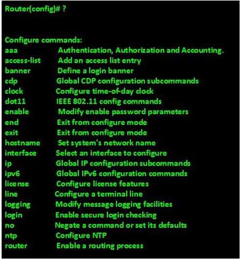
We can use this command when we are unsure of the correct command to use or we have made an error.
We can also use the <tab> key to autocomplete commands. This may be useful when the command is too long and used frequently. However, we recommend that as we are beginning to learn the IOS, we should use the full command till at a later stage.
There are other shortcut keys used and these are shown below.
- Ctrl-R – to re-display a line
-
Ctrl-Z – exit the configuration mode and returns the user to the user exec mode.
- Down and up arrows – these are used to scroll through previously entered commands.
- Ctrl-Shift-6 – this command is used to interrupt a command that has been issued.
- Ctrl-C – this command can be used to abort a configuration line and return to the privileged mode.
There are other basics that are used in CISCO IOS, however, these we will learn as we continue in this course.
NOTE: you will be expected to know and memorize all the commands used in this course for the exam. In the ICND 1, ICND 2 and CCNA composite exams, the use of these commands will be frequent and you will NOT have anywhere to refer to.
Examination commands
When configuring a router, you may need to troubleshoot different configurations. The use of examination commands is vital in this respect. The examination commands are viewed in the privileged executive mode and will start with “show” in the prompt. Some of these commands and their functions are shown below.
- Show version – shows information on the CISCO IOS running on a router or a switch. Such as the version, release date.
- Show startup-config – this command shows the configuration file that is stored in the NVRAM.
- Show running-config – the commands that are currently being used by the router for its operation can be viewed using this command. This information is usually stored in the router’s RAM.
Network simulation using packet tracer

As mentioned earlier, access to physical network devices may at some times be difficult, and since this course is based mainly in a lab environment where we need to access and configure these devices, we need an alternative.
Your instructor should be able to give you access to packet tracer. A program that can be used to simulate networks in the lab environment. This software will give you access to most if not all, commands and devices needed in CCNA. In this course, we will use packet tracer and real devices in configurations.
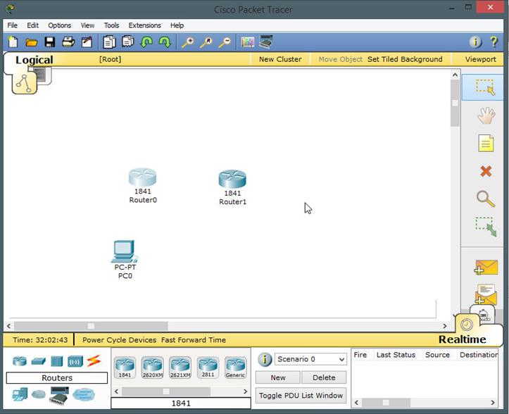
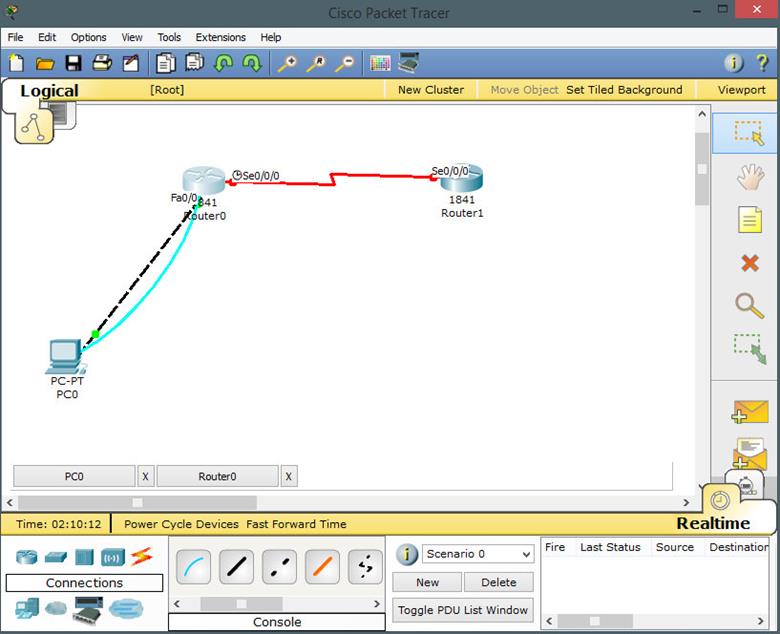
After installation, the main window of packet tracer will be as shown below. 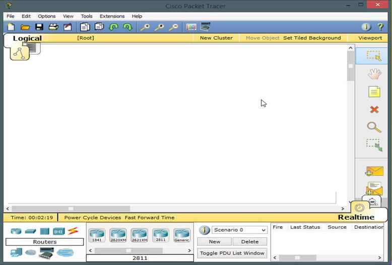
Familiarize yourself with the software. At the bottom left, we have the various categories of devices that may be used in the network. These include routers, switches, and connections among others. Clicking on any of these icons will bring a list of more devices in each category.
To use a device, simply click on its icon and drag it to the main work area shown in white.
On the right hand side, near the bottom, there are two icons in the shape of envelopes. These icons are used to capture packets and you will use them at a later stage. As you continue to use this software, you will become more and more experienced and gradually you will know all the capabilities and functions.
The scenario
In this chapter, we will configure 2 routers and 1 host PC in packet tracer. This will be basic configuration, aimed at showing you the main features of IOS and immersing you into the CISCO configuration environment using packet tracer.
The topology shown below shows 2 routers and a PC. The connection from the PC to router R1 is done using a crossover cable while the interconnection between the two routers is done using a serial cable.
The serial interface on R1 is the DCE side while the connection on router R2 is the DTE side. If you are using physical devices you should be aware of this cabling.
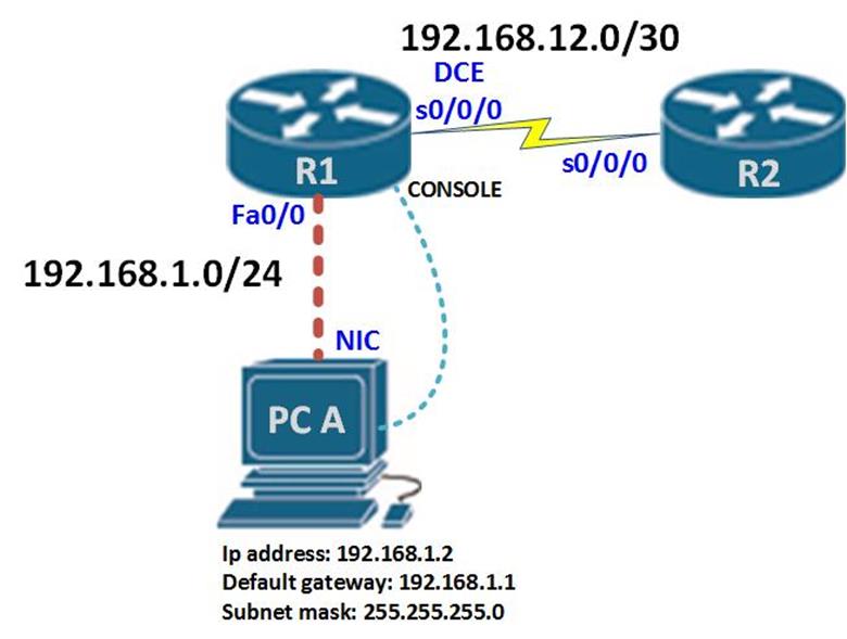
In this topology, we have 2 routers labeled R1 and R2. We have a connection between them which is S0/0/0 DCE on R1 and S0/0/0 on R2.
Router R1 is connected to PC A through 2 interfaces. One is the console port which will be used to configure the router, while the other will be the network port to PCA’s NIC via Fa0/0 on R1.
In packet tracer, the diagrams shown below are a guide to making this topology.
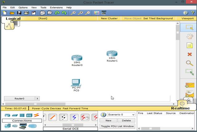
Step 1:
Drag and drop into the main work area the devices that will be used in the configuration as shown in the topology. In this case we use 2 1841 CISCO ISR routers. By default they are labeled Router0 and Router1. Also in the end device section drag and drop a PC icon, as shown in the diagram.
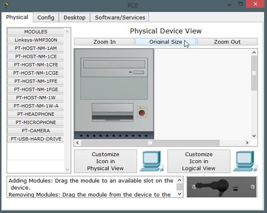
Step 2:


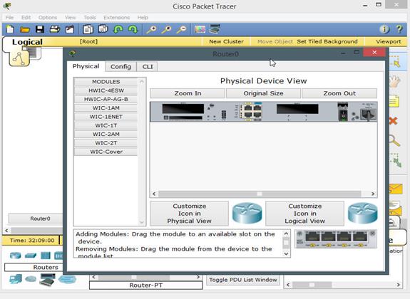
Click on the router0 icon. A new panel opens up and details the back panel of the router. At the top, there are three tabs – physical, config, CLI. In this case we are interested in the physical. This router, does not have a WAN connection interface as shown in the part highlighted by the red arrow. We need to install the WAN interface module on both routers so that we can interconnect them using serial links.
To do this, we have to shut down the router and look for the appropriate module on the left which can be used for serial WAN connections. To turn off the router, you need click the switch button shown by the blue arrow in the diagram above.
Step 3:
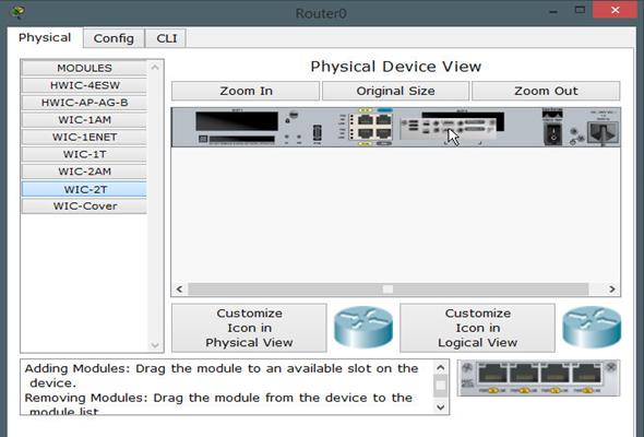
We need to add the correct WAN module. From the left to the panel on the right highlighted by the red arrow in the previous diagram. In this case and most other scenarios, we will be using the WIC-2T module highlighted in red. Drag and drop it to the empty space as shown above.
NOTE: the router goes off when the power button is switched. After installing the module you need to switch it back on.
Step 4:
Next we need to connect the devices with the correct cable. The connection from the PC to Router0 uses a crossover cable while the connection between the two routers uses a serial DCE cable. In the connections tab at the bottom make sure you use the correct cable.
To connect devices:
- Select a cable by clicking on it.
- Click on the device you want to connect to
- Choose the correct interface number
- Repeat process on the other end of the cable by dragging it to the opposite device and clicking on the correct interface.
These steps are shown in the diagrams below
The connections shown are for router0 and router1.
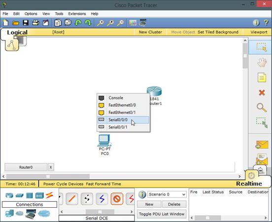
Connection on Router0 shown above using serial0/0/0
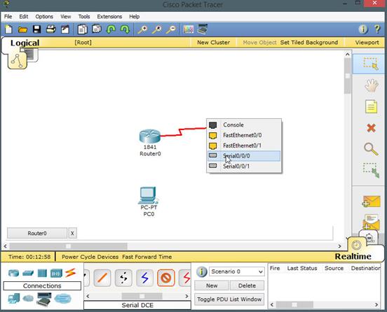
The connection on Router1 using serial0/0/0 there are two connections from PC0 to Router0. One connection shown by the black dotted line is the LAN interface on PC0’s fastethernet interface while the blue one is the console cable used to configure Router0 as shown below.
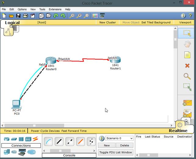
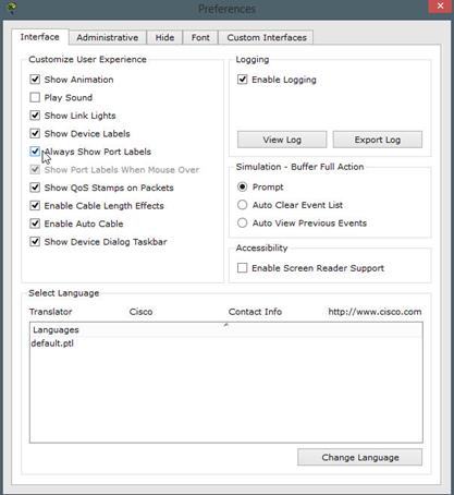
As you can see from the diagram above, the interface labels are visible. To enable this, go to options, then click on preferences and in the preferences tab select the option that says “always show device labels” as shown below marked by a red arrow.

The console cable connects to the RS 232 port on the PC and the console port on the router.
Now that we have interconnected the devices, we need to access the CLI interface on the router from the PC0.
To do this, we need to click on PC0’s icon. Whereby we will receive this output.

As mentioned earlier, packet tracer simulates the operation of different network devices, in we click on the desktop tab, we will see the same options as we would a physical computer.
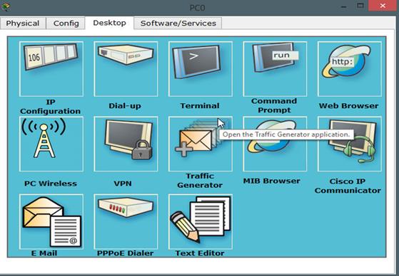
In this tab, we have several options such as the ip address configuration, the terminal and command prompt among others. In this case we will use the prompt which will connect us to the routers CLI.
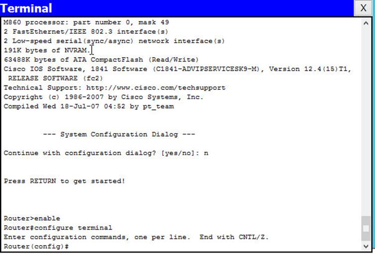
After clicking the terminal tab, leave the configurations options on default and click OK. This will connect you to the router in its boot-up process shown by the several “#” output.
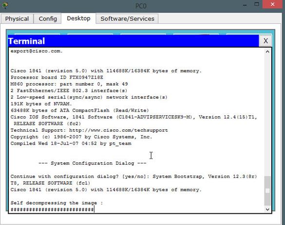
After the boot-up process is complete, you should receive a command prompt shown below. Type in “no” and press enter.

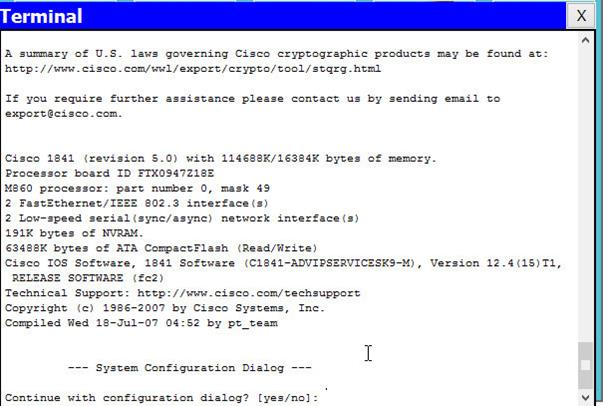
After this prompt, we will enter the user exec mode. As we mentioned earlier, this is the first access point in the CISCO IOS CLI.
It is denoted by the output:
Router>
To enter the privileged configuration mode we should type in “enable” and enter. This will take us to the privileged executive mode denoted by the output shown below.
Router#
In this mode we can do various troubleshooting commands such as show and debug commands.
Next we need to access the global configuration mode so that we can begin our configuration. To do this, we need to type in:
“configure terminal” followed by ENTER. This will take us into the global configuration mode which is shown in the prompt output as:
Router(config)#
NOTE: if you are using real devices, the steps followed should be the same, and the output received should not be different. However, if you need more information, contact your trainer.


Configuration
In this section, we should configure the following.
- Hostname on router0
- Limit access to the router
- Configure banners
- Disable ip domain lookup
- Configure the interfaces
- Verify the configuration
- Test local network connectivity
- Document the network
The commands used will be done mainly from the global configuration mode on router0. We will not configure Router1 but the same concepts will be used. Keep this in mind.
Hostname on Router0
In the topology diagram, the first router was R1 not Router0, when naming routers, remember to only use alphanumeric symbols and the underscore only. There should be no space between the names because this will return an error.
To change a hostname of a router or a switch the command needed in the global configuration mode is:
Router(config)# hostname <NAME_OF_ROUTER>
The parameter shown in angle braces will be the name used on the router or switch.
In this scenario, In the global configuration mode on Router0, the command needed to change the name of this router from Router0 to R1 will be:
Router(config)#hostname <R1>
After entering this command, you should be able to see the change reflected immediately from:
“Router(config)# ” to “R1(config)#”
Now with that command we have successfully changed the name of the router.
Limit access to the router
The next thing we need to do is to limit access to the router. We need to do this so as to strengthen the security. Every device should have locally configured passwords to limit access.
We have seen that the CISCO IOS is organized hierarchically. One of the reasons behind this is to enhance security. In this respect we need to configure security on our router. The passwords we will configure are to require authentications at various points on our routers. The passwords we will configure are:
- the console line password – to limit connection to the router using the console port
- the enable password – to limit access to the privileged Executive mode
- enable secret password – to configure encrypted passwords to protect the privileged EXEC mode
- VTY lines password – to protect access to the router via telnet
- Console line
We first need to secure the console lines. As we saw earlier, the console lines allow access to configuration of the router through the router’s console port. To do this, we need to access the console line in the global configuration mode.
The command to access the console line is:
Router(config)# <line console 0>
The first line is usually 0 as shown above. After entering this command, we will enter the specific configuration mode for the console line which is shown below:
Router(config-line)#
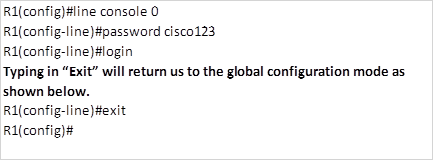
From this mode, we need to enter a password and also a command to require authentication before accessing the console line. The commands needed to do this are:
Router(config-line)#password <cisco>
Router(config-line)# login
The first line specifies that the password for the console on this router is “cisco” and the second line – “login” states that for anyone to access this router, you will need to enter a password to access the CLI using the console port.
To verify this command, the next time someone tries to access this router after it is rebooted, they will be required to enter this password.
In this scenario, we will use the password “cisco123” and the commands needed on R1 will be
- Privileged exec mode – enable password
The privileged executive mode allows us to access the global configuration commands, therefore, it is important to secure this mode so as to limit access.
To do this, we need to configure the “enable password” on the router’s global configuration mode. This will require the use of a password to enter the privileged executive mode.
In the global configuration mode enter the following:
Router(config)#enable password cisco
The above command specifies that to be able to access the privileged access mode, the user has to enter the password cisco in the user exec mode.
On R1, we configure the password “cisco1” for the privileged executive mode using the following command.
R1(config)#enable password cisco1
To verify this command, enter the command “end” to return to the privileged exec mode, then enter the command “disable” to return to the user exec mode.
To login to the privileged exec mode on R1, you will be required to enter the password “cisco1”.
- Enable secret command
The use of the enable password, is not secure since the password is stored in the flash memory as plain text and it can be easily cracked. To enable a more secure password for the privileged exec mode, we use the enable secret command.
The enable secret command will create an encrypted password.
To enter this command on a router use the following command:
R1(config)#enable secret <cisco12>
This specifies that we should use an encrypted password of “cisco12”
If we use this command on R1, it will override the enable password and replace it with the secure password. To do this on R1 enter the following command.
R1(config)#enable secret cisco12
- Vty lines
We also need to limit remote access to the router, the vty lines allow access to a router via Telnet. By default, many Cisco devices support five VTY lines that are numbered 0 to 4. A password needs to be set for all available vty lines.
To enable a password for the telnet lines, we need to enter the specific configuration mode for these lines. To do this, we enter the command shown below:
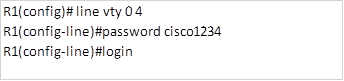
R1(config)#line vty 0 4
The above command specifies that we want to configure the 5 telnet lines on this router. After entering this command, we will enter the vty lines configuration mode shown by the prompt below.
R1(config-line)#
In this mode, we can configure the password and require authentication when a user wants remote access to a router. The commands needed to accomplish this are:
R1(config-line)#password <telnet_password>
R1(config-line)#login
The commands above specify that this router should be configured with a password and should require authentication with said password for access.
On R1, to secure the vty lines using the password cisco1234, the commands needed to accomplish this will be:
- Encrypting Password Display
The commands that we have used to configure the passwords are insecure since the passwords are stored in plain text. To enhance the security of the passwords that we have configured, we use the command “service password-encryption“. When this command is executed, the plain text passwords will be encrypted. This means that they one cannot see the password in plain text from the running- config.
To configure this on router R1, enter the command shown below in the global configuration mode:
R1(config)#service password-encryption
This will ensure that no password can be viewed from the running configuration.
Configure banners
Configuring passwords is a good measure to protect the router from unauthorized access. However, we also need to warn would be attackers.
Banners are a way in which we notify unauthorized personnel who would want to access the router. In some cases, failure to apply banners can cause attackers to escape legal ramifications since they can argue that there was no information against unauthorized access.
One way to configure the banner is using the MOTD (message of the Day). To do this, we need to enter the command shown below in the global configuration mode:
R1(config)#banner motd <# insert message in here #>
The # in the banner motd command denotes the beginning and end of the message to be displayed.
On R1, to configure a banner that states “!!!! WARNING, AUTHORIZED ACCESS ONLY!!!!” the command shown below will be used.
R1(config)banner motd #!!!! WARNING, AUTHORIZED ACCESS ONLY!!!! #
Once the command is executed, the banner will be displayed on all subsequent attempts to access the device until the banner is removed.
Configure the interfaces
In this scenario, there are 2 interfaces on R1 and 1 on the PC0 that we need to configure. The addressing scheme used is shown below.
| Device | Interface | Ip address | Subnet mask | Default gateway | |
| PC0 | FastEthernet | 192.168.1.2 | 255.255.255.0 | 192.168.1.1 | |
| R1 | FastEthernet0/0 | 192.168.1.1 | 255.255.255.0 | ||
| Serial0/0/0 | 192.168.12.1 | 255.255.255.252 | |||
We will not configure Router1. When configuring the PC, the following steps should be taken:
- Click on the PC0 icon
- Click on the desktop tab
- Click on the ip configuration tab
- Enter the values shown above
- Close the ip configuration tab
On the router, we need to configure the interfaces and also activate them. By default, interfaces on routers are usually deactivated.
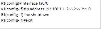
To configure the interface on a router, the following commands will be used.
Router(config)#interface <interface_name><interface_number>
Router(config-if)#ip address <interface_ip_address> <subnet_mask>
Router(config-if)#no shutdown
Router(configu-if)exit
- In the above configuration, the first line is used to enter into the specific interface configuration mode. This will allow us to enter various interface configuration options.
- The second line will assign the ip address and the subnet mask according to the specifications
- The third line will activate the interface and make it usable.
In this scenario, we have 2 interfaces on R1. To configure R1’s FastEthernet0/0 interface, the following commands will be used:
To configure the serial interface the following commands will be used.
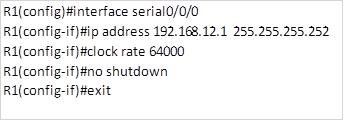
As you can remember, we connected the router R1 using a serial DCE cable, this means that this interface must have a clocking signal simulated as you would using a CSU/DSU. The command:
Clock rate 64000 above, specifies that this interface is the DCE side and it has a clock rate of 64000.
In packet tracer, after configuring the interfaces and executing the “no shutdown” command, the end points on the fast Ethernet link from the PC0 to R1, should turn from red to green as shown in the figure below:

Verifying the configuration
After all these configurations are done, we need to verify that they have been executed as well as save the configuration to the NVRAM from the RAM.
To save the configuration, we need to exit to the privileged executive mode and enter the following command:
Router#copy <running-config> <startup config>
The command above when executed will save the running configuration to the NVRAM of the router, this will make the running configuration the startup-configuration in the next boot-up of the router.
On R1, the command needed to save the running configuration to the flash memory will be as shown below.
R1#copy running-config startup-config
After saving the configuration, we also need to verify the operation of the router, as well as check for connectivity to our host PC.
The verification commands we will use will also be used when troubleshooting. More on troubleshooting will be discussed in subsequent chapters.
In this chapter, we will check for the interface configuration, the running configuration, and the connectivity to the PC using ping command.
The running-configuration
After configuring the router, we need to check all the configurations used, to do this we need to check the running configuration. The running configuration as we mentioned earlier is stored in the RAM and therefore, any additional commands we make will need to be saved to the startup configuration.
The running configuration will show us all the commands that we have used while configuring a device.
The command used to check the running configuration is executed in the privileged executive mode and it is shown below.
router# show running config
When executed, this command will show us all the configuration commands used on a router or a switch.
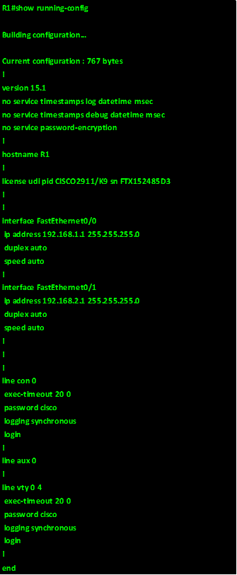
The output of the show running-config on R1 is shown in the exhibit below:
Verify interface operation
When verifying the interfaces on routers, we need to check whether they are operational and whether they have been assigned the correct ip addresses. To accomplish this, we will use the commands shown below in the privileged executive mode:
- Show ip interface brief
- Show interface <interface name> <interface number>
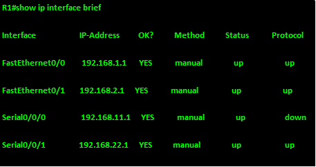
Show ip interface brief
The output of this command will show the operational status of an interface at layer 1 and layer 2. The output shows the interface, the ip address assigned, the status, and the status of the protocol which is connectivity at layer 2. If the interface is operational, the status and protocol should be up/up.
Show interface <interface name> <interface number>
The output of this command shows the status of the specific interface as shown in the output below for interface FastEthernet 0/0.
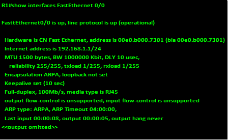
As you can see from the above output, the interface is shown as on and it is operational. This is another way we can verify the status of an interface.
Summary
In this chapter, we have looked at the basic configuration in CISCO IOS. We have configured a router in packet tracer given the requirements of the lab. We have also looked at the command structure of IOS. In the next chapter, we will begin routing by looking at how routing works and configuration of static routes.