


Introduction
In previous chapters, we learnt how VLANs segment broadcast traffic on a switch and segment a switched network into different LANs, we also learnt how VLAN information can be transmitted to other switches in the network using VTP and how we can avoid layer two loops using STP.
Consider, this, as the network administrator, one of your tasks is to create and assign different users to VLANs in your network, you have three main departments which should be logically segmented using VLANs, VLAN 10 – FINANCE, VLAN 20 – SALES and VLAN 30 – HR.
The use of VLANs means that users would not be able to communicate across departments, i.e. a user in FINANCE, would not be able to send a message to a user in SALES since they are on different broadcast domains.
In many enterprises, you will find that information sharing across departments is a requirement, therefore, the question begs, how do you make users in the SALES and FINANCE department communicate, yet they are on different VLANS?
In this chapter, we will discuss the role played by inter-VLAN routing in communication between different VLANs. We will learn how it works, consider the various methods that can be used to implement it, configure inter-VLAN routing using router-on-a-stick and traditional inter-VLAN routing, compare the two styles of implementation and finally verify and troubleshoot inter-VLAN routing.
Introduction to inter-vlan routing
When we learnt about VLANs, we said that each VLAN is usually on its own subnet, switches mainly operate at layer 2 of the OSI model and therefore they do not examine the logical addresses. Therefore, user nodes located on different VLANs cannot communicate by default. In many cases, we may need connectivity between users located on different VLANs. The way this can be accomplished is through inter-VLAN routing.
In this course, we will look at one type of inter-VLAN routing, which is through the use of a router.
Definition
Inter-VLAN routing can be defined as a way to forward traffic between different VLAN by implementing a router in the network. As we learnt previously, VLANs logically segment the switch into different subnets, when a router is connected to the switch, an administrator can configure the router to forward the traffic between the various VLANs configured on the switch. The user nodes in the VLANs forwards traffic to the router which then forwards the traffic to the destination network regardless of the VLAN configured on the switch.
The figure below, shows how this process works.
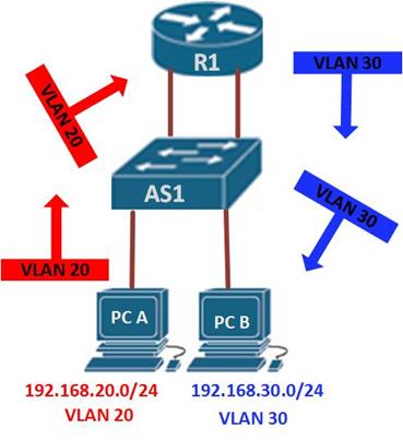
Information destined for PC B, leaves PC A with the VLAN 20 tag, when it gets to R1, the router, changes the format of this message from VLAN 20, to VLAN 30, it then sends it back to the switch and the switch finally sends the message to its intended recipient PC B.
There are two ways in which inter-VLAN routing can be accomplished.
- Traditional inter-VLAN routing
- Router-on-a-stick
Traditional inter-VLAN routing
In this type of inter-VLAN routing, a router is usually connected to the switch using multiple interfaces. One for each VLAN. The interfaces on the router are configured as the default gateways for the VLANs configured on the switch.
The ports that connect to the router from the switch are configured in access mode in their corresponding VLANs.
When a user node sends a message to a user connected to a different VLAN, the message moves from their node to the access port that connects to the router on their VLAN. When the router receives the packet, it examines the packet’s destination IP address and forwards it to the correct network using the access port for the destination VLAN. The switch now can forward the frame to the destination node since the router changed the VLAN information from the source VLAN to the destination VLAN.
In this form of inter-VLAN routing, the router has to have as many LAN interfaces as the number of VLANs configured on the switch. Therefore, if a switch has 10 VLANs, the router should have the same number of LAN interfaces.
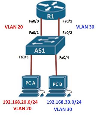
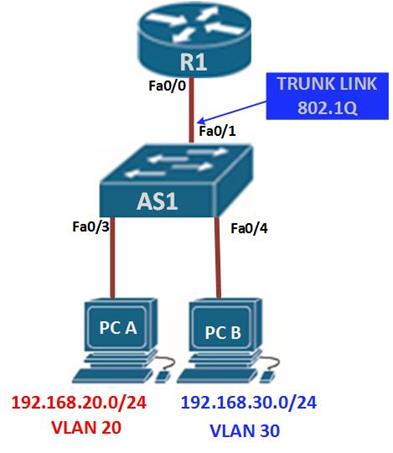
Take the scenario shown below.

If PC A in VLAN 20, wanted to send a message to PC B in VLAN 30, the steps it would take are shown below.
- PC A would check whether the destination IPv4 address is in its VLAN if it is not, it would need to forward the traffic to its default gateway which is the ip address on Fa0/0 on R1.
- PC A then sends an ARP request to AS1 so as to determine the physical address of Fa0/0 on R1. Once the router replies, PC A can send the frame to the router as a unicast message, since AS1 has Fa0/0’s MAC address, it can forward the frame directly to R1.
- When the router receives the frame, it compares the destination IP address by referring to its routing table so as to know to which interface it should send the data towards the destination node.
- The router then sends an ARP request out the interface connected to the destination VLAN in this case out Fa0/1, when the switch receives the message, it would flood it to its ports and in this case, PC B would reply with its MAC address.
- R1 would then use this information to frame the packet and finally send it to PC B as a unicast frame.
Configuring traditional inter-VLAN routing
In this section, we will configure Inter-VLAN routing on the router and the switch using the scenario we have just seen above. All the VLANs are active and the PCs have been assigned ports, our configuration will only be limited to the router’s inter-VLAN configuration and the switch ports connecting to R1.
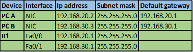
The ip addressing in use is shown below.
Testing connectivity using the ping command should reveal that PC A cannot ping PC B.
The first step is to configure the switchports to access the specified VLAN, fa0/1 to VLAN 20 and fa0/2 to VLAN 30. This is accomplished using the commands shown below.
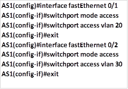
This is the only configuration on the switch, once this is done save the configuration and move on to the router.
On R1, we need to configure its interfaces with the default gateways corresponding to the VLANs. That is; on fa0/0 -192.168.20.1/24 and on fa0/1 – 192.168.30.1/24. We accomplish this using the commands shown below.
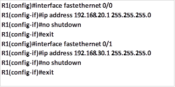
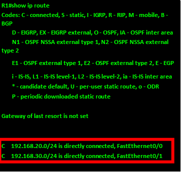
With this configuration we should save and test for connectivity on PC A and PC B, by using the ping command, and the results should be successful. Examining the routing table of R1 should show us the two routes as shown in the output below. This confirms that the router knows of the two VLANs and therefore traffic can flow between them.
Inter-VLAN routing using router-on-a-stick
With the example shown above, there are several concerns, suppose we had 10 or even 20 VLANs configured on the switch, even if the switch has enough ports to support the connection to the router, it is highly unlikely that the router would have so many Ethernet interfaces. Therefore we need a way to use the limited router interfaces to support routing between many VLANs that may be on a switch.
Introduction to Router-on-a-stick
In the second type of inter-VLAN routing which is Router-on-a-stick, the router is connected to the switch using a single interface. The switchport connecting to the router is configured as a trunk link. The single interface on the router is then configured with multiple IP addresses that correspond to the VLANs on the switch. This interface accepts traffic from all the VLANs and determines the destination network based on the source and destination IP in the packets. It then forwards the data to the switch with the correct VLAN information.
As you can see in the diagram below, the router is connected to the switch AS1 using a single, physical network connection.
In this type of inter-VLAN routing, the interface connecting the router to the switch is usually a trunk link. The router accepts traffic that is tagged from the VLANs on the switch through the trunk link. On the router, the physical interface is divided into smaller interfaces called subinterfaces. When the router receives the tagged traffic, it forwards the traffic out to the subinterface that has the destination IP address.
subinterfaces aren’t real interfaces but they use the LAN physical interfaces on the router to forward data to various VLANs. Each subinterface is configured with an IP address and assigned a VLAN based on the design.
Configuring inter-VLAN routing using router-on-a-stick
In this section, we will configure inter-VLAN routing using router-on-a-stick and using the topology shown below. It has been modified by adding additional VLANs so as to show the effectiveness of using router-on-a-stick as opposed to traditional inter-VLAN routing.
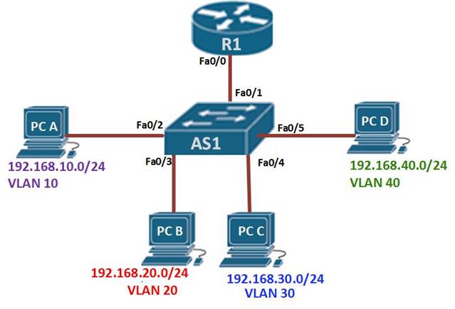
In our scenario, we have four hosts located on 4 VLANs, the native VLAN is VLAN 99. Our task is to configure inter-VLAN routing on the router and the switch and ensure that all devices can communicate at the end of the lab. The Ip addressing scheme for the topology is shown below.
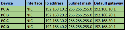
NOTE: Unlike traditional inter-VLAN routing, when using subinterfaces, we do not assign an ip address to the interface on the router that is connected to the switch.
In this lab, the configuration on the PC’s and the switch ports connecting to them is done correctly, our task is to configure the interface fa0/1 on AS1 and configuration on R1.
Step 1.
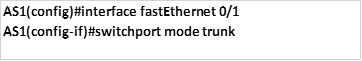
On switch AS1 we need to define the interface connected to the router as a trunk link. This will allow traffic from all VLANs to get to the router using that interface. The command to accomplish this is on AS1 is:
NOTE: many errors may rise if the switchport connected to the switch is not configured as a trunk.
Step 2.
At this step inter-VLAN routing can be configured on the router. As we mentioned earlier, when configuring router-on-a-stick, we use subinterfaces.
Each subinterface is created using the interface interface_id.Subinterface_id in the global configuration mode. As shown below.

NOTE: the “.” Between the interface ID and the subinterface ID is a must. The subinterface ID is a logical number but ideally it should describe the VLAN ID.
To create a subinterface which will be used to route for VLAN 10, we will use the command shown below.

This will take us into the subinterface configuration mode which is denoted by the prompt shown below.

In the subinterface mode, we can link the VLAN ID to this interface as well as assign it an ip address and a subnet mask.
Step 3.
To link the subinterface with the specific VLAN, we use the command “encapsulation dot1q <VLAN_ID>” this will specify that this interface will get traffic from the specified VLAN. In our example, the command needed to link VLAN 10 to this subinterface is shown below:

Step 4.
In this mode, we can also assign the subinterface with the ip address and subnet mask which will be used for VLAN 10. The default gateway on the PC’s will be used as the interface address as shown below.

Step 5.
When all the subinterfaces have been assigned to their respective VLANs, we need to activate the LAN interfaces that they are connected to by issuing the no shutdown command.
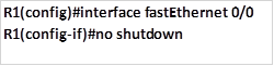
This will activate the interface and allow for inter-VLAN routing.
NOTE: the native VLAN is used to carry untagged traffic, the configuration for the native VLAN subinterface on the router is done using the command shown below.

The native keyword is used to identify the specified VLAN as the native VLAN.
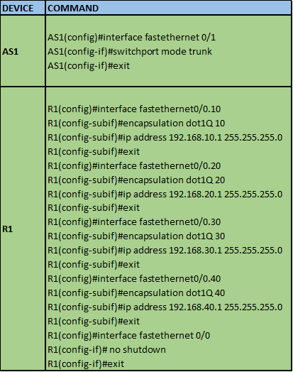
In our scenario, the commands needed to configure inter-VLAN routing using router-on-a-stick are shown below.
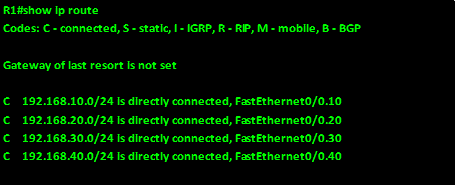
With this configuration, we should be able to communicate between the different VLANs. The output of the show ip route command should confirm that we are connected to all four routes as shown in the output below. Running the ping command should give us replies for all routes in the routing table.
Comparison of router-on-a-stick and traditional inter-VLAN routing
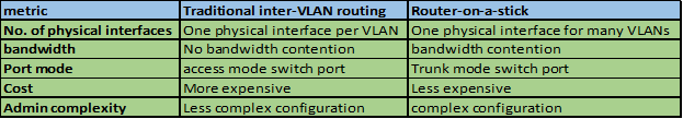
In this table, we have compared router-on-a-stick and traditional inter-VLAN routing.
NOTE: in the CCNA exams, understanding inter-VLAN routing is very important, the focus is mainly on router-on-a-stick inter-VLAN routing, however, you should not ignore the traditional inter-VLAN routing.
Verifying and troubleshooting inter-VLAN routing issues
In this section, we will try to understand some of the common problems associated with inter-VLAN routing using router-on-a-stick configuration.
In verifying inter-VLAN routing, the commands mostly used are:
- Show run
- Show ip interface brief
- Show interface <interfaceID.subinterfaceID>
The output of the show interface <interface_ID.subinterface_ID> should give you output similar to what is shown in the output below.
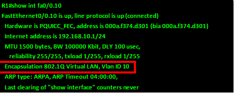
From the output above, the VLAN ID, the encapsulation, and the status can be verified using this command. The section highlighted in red shows the encapsulation type and VLAN ID.
Most of the errors that you may encounter when dealing with inter-VLAN routing are misconfiguration errors in the subinterfaces. However, by using the step by step guide shown and the verification and troubleshooting commands you can be able to quickly resolve any issues.
Summary
In this chapter, we have looked at how we can make users located on different VLANs communicate, we have looked at traditional inter-VLAN routing as well as inter-VLAN routing using router-on-a-stick. We also compared the two methods and configured them.
For the most part of this course, we have been primarily focused on LAN technologies, many enterprises span over large geographical distances. In the next few chapters, we will discuss WAN technologies and understand how they work.