


Overview
In our previous chapters, we have looked at the OSI and TCP/IP models in detail and explained how they aid in communication. All these concepts lead up to this chapter and beyond. In this chapter, we will learn how to plan our networks and look at the various cabling options to use in our networks at the end of this chapter, we should also learn how to plan for the IPv4 addressing we will use in our networks.
Introduction
There are many considerations to make when planning the network. In this section we will consider the LAN connections and the WAN. The choice of which router to deploy is determined by the Ethernet interfaces that match the technology of the switches at the center of the LAN. The internetwork devices that we will be using in this course will be primarily routers and switches.
Router
The routers in our networks are used to interconnect the various LAN networks. Each LAN is usually connected to others using an interface on the router. The router has various LAN interfaces that it connects to these segments. Therefore, when choosing a router, you should consider the number of LANs in your global network. The router should also have interfaces that connect to outside interfaces such as to an ISP.
The figure shown below shows the various ports that can be found on a router as well as explanations on their use.


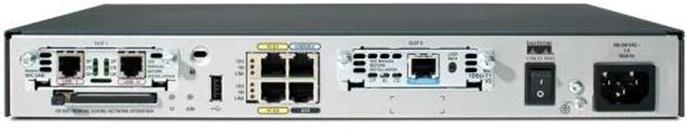


- The fast Ethernet interface will be used to connect to our LAN networks while the serial interface will be used to connect to the WAN.
- The console port is the main configuration port on a router, and it is where we will connect to the router and issue configuration commands through. The auxiliary port shown as aux port is used as an alternative to the console port.
- The power button on a router is used to turn on and off the router.
Switch
The switch will be used to connect to the various end user devices in our network. These may be PCs, notebooks, IP phones among others. The switch is connected to the router using one of its interfaces so that other networks can be reached through the router.
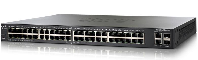
The image shown below shows a 48 port CISCO switch.
Device selection factors
In our networks, there are several factors that will affect which devices we will install. These factors may affect network performance and may be influenced by the factors shown below.
Cost – the various models of CISCO routers and switches, the choice of router or switch may be influenced by the budget that the organization may have.
The speed of the ports on a device may influence the decision to install a particular device. We will learn about the various speeds and how they influence the network performance in upcoming chapters.
Other factors that may influence our choice of device are the manageability of a device, support, durability, whether it has expansion bays, among others.
Whatever device is chosen for your network, however, the successful implementation of the network will depend on the configuration and careful planning that has been done.
Cabling the network
Cabling factors
When cabling the network there are several factors to consider.
- The length of the cable
- Telecoms room
- Backbone and distribution cabling
- Environmental factors
The length of the cable is one of the most important factors to consider. In most networks we will use the UTP (Unshielded Twisted Pair) cable. This cable is made of copper the range should be limited to 100 meters.
Telecommunications room – in many organizations, this is the central area where intermediary devices such as routers, backbone switches, among others are located. The cabling in this room should be correctly labeled so as to avoid misconfiguration and other problems.
Backbone cables are the cables used to connect to devices such as servers, distribution cables connect to end user devices and are mainly straight through UTP cables.
When cabling the network, there are several types of cables that may be used. We will discuss the use of the UTP cable and the serial cables.
UTP cable
The UTP cable will be used to connect the following devices
- Router to router – depending on scenario
- Router to switch
- Router to PC – or other hosts end devices
- Switch to switch
- Switch to hosts.
These configurations use three main types of UTP cable configurations which are.
- Straight through
- Cross over
- Rollover cable
TIA/EIA governs the UTP cabling standards, the figure below shows an example of the UTP cable. It has four pairs of cables with different color codes.
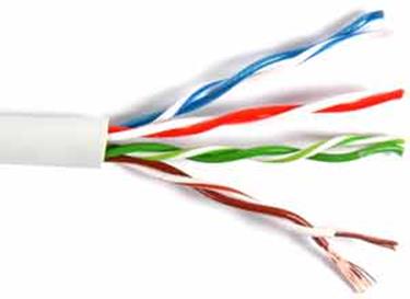
There are 8 wires in pairs. These are
- Blue
- White+blue
- Orange
- White+orange
- Green
- White+green
- Brown
- White+brown
The two T568 standards i.e T568A and T568B, determine the arrangement of these wires so as to suit the various configuration needs.
T568A and T568B arrangements are shown in the image below.
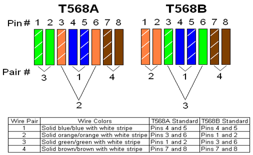
These configurations are constant and cannot change.
- Straight through configuration – both sides of the UTP cable have the same standard i.e both are either T568A or T568B.
- Crossover cable configuration – one end is T568A the other end T568B.
Where to use these cables
The straight through cable is used to connect devices that work on different layers of the OSI models. i.e
- Routers and hosts such as PCs work on layer 3 – logical addressing
- Switches work on layer 2 – physical or MAC addressing
Therefore, to interconnect a router to a switch or a switch to a PC, we use a straight through cable.
To interconnect devices working on the same layer in the OSI model, we use crossover cables. Ie – switch to switch, router to router and router to PC.
The table below shows the various connections used in the LAN using these standards.
| Device 1 | Device 2 | Cable type |
| Router | Router | Crossover cable |
| Router | Switch | Straight through cable |
| Router | PC | Crossover cable |
| Switch | Router | Straight through cable |
| Switch | PC | Straight through cable |
| Switch | Switch | Crossover cable |
The rollover cable
The rollover cable is used to configure the router. This is shown below. This cable has a special configuration as shown.
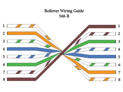
There are different router models and as such they determine the connector used on the rollover cable.
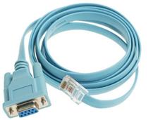
The RJ45 connector side is connected to the router, while the other side connects to the PC’s port. This will be discussed in the next chapter when we will be doing the basic configuration.
These are the standards used in cabling in the LAN. When it comes to the WAN, we will use the serial connections.
Serial connections
Serial connections are used to connect the gateway router to the external network such as the ISP or the internet. There are several standards that are used in serial connections, however, we will focus on the V.35 cable.
In the labs in this course, we will use the V.35 cable with a 60 pin connector to the router’s side. This cable comes in two specifications.
In the real world, the male side of this cable which has 15 pins is usually connected to a CSU/DSU device to provide clocking. However, in lab environments, the male side of this cable is connected to the female V.35 cable to simulate a CSU/DSU connection.
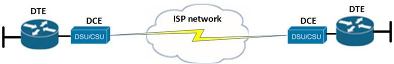
In the WAN environment, the following terms are used to describe the types of devices and connections used.
DCE – this is a device that provides a clocking signal to the router from the WAN service provider.
DTE – typically the router will serve as the DTE device in our networks. It is the device that receives the clock rate from the DCE.
The CSU/DSU device is the device that provides the clock rate and is considered the DCE.
NOTE: we will discuss more on the WAN connections in the chapters on connecting to the WAN.
The figure below shows the serial V.35 DTE cable
The figure below shows the V.35 DCE side cable
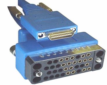
In the lab environments such as the ones we will be running our labs in, the V.35 DCE cable will connect to the router which will be providing the clocking signal while the male side will connect to the DTE as shown in the figure below.

Lab environments
NOTE: in our lab environments we will simulate the clocking signal on the routers therefore we will use a different type of serial connection. In this case we will use a serial DCE cable and a serial DTE cable. Normally in real world scenarios, routers are the DTE devices while the CSU/DSU the DCE. However, since this is a lab environment we can use a router as a DCE device. The real world use of serial cables is shown below.
The serial DCE cable is a V.35 serial cable with one male Winchester on one end and a female connector on the other end. This is shown below.
Developing an ip addressing scheme
Developing an IP addressing scheme is one of the most important tasks that you as a network technician are supposed to be perform. There are several factors that are to be considered in this respect.
- The current needs
- The number of devices needing ip addresses
- The future needs
When developing an addressing scheme for a network, the first task is to determine the number of host or end user devices in the network. These may include: IP phones, servers, User PCs among others.
We also need to consider the number of internetworking devices and interfaces on those devices that may need ip addresses. These may include: router LAN interfaces, WAN interfaces, firewalls among others.
The third consideration we need to make is for the devices in our networks that may need management ip addresses. These IP addresses are the means to connecting to devices that we need to configure such as switches and wireless access points.
For these devices, we need to list all the categories of devices and determine the number of ip addresses that are needed. We also need to account for future growth of the network.
After this determination, we need to recall the formula for the number of host ip addresses as learnt in the chapter on addressing in IPv4.
The formula is 2^n- 2= number of host addresses, where n is the number host bits we need.
Another consideration that we need to make is the number of subnets that we require in our networks.
Remember:
- Each connection to a router from our LANs is supposed to be on a separate subnet. The IP address that is configured on the router’s LAN interface is usually the default gateway for the devices in that subnet.
- The interconnection between the routers on the WAN links is supposed to be on its own subnet.
Given a particular addressing space, the formula to calculate the number of subnets we require is “2^n” where n are the bits that have been borrowed from the host portion.
The next step, after subnetting is to apply the appropriate subnet mask for the different subnets in our network.
The last step is proper documentation of the IP addressing scheme. This is necessary so as to avoid misconfiguration issues as well as to simplify troubleshooting when issues arise.
NOTE: we will learn how to properly assign ip addresses in subsequent chapters.
Summary
In this chapter, we have looked at how we plan and cable our network. We looked at the role of various devices in the network including the router and the switch. We also looked at the different connections used in the LAN and the WAN. We concluded by refreshing our knowledge of IPv4 addressing by planning the subnet for use in the network. In the next chapter, we will do the basic configuration of a router. This will lead into the routing chapters.