


Introduction
In the last chapter, we discussed some of the concepts that make the WAN work, we briefly described some of the protocols in the WAN. In this chapter, we will discuss serial links and the physical connections we use. We will then explore the default encapsulation on CISCO routers which is HDLC and finally discuss how to troubleshoot a serial connection.
How serial communications work
When communicating data, there are two types of transmissions that can be used; parallel and serial communication. In our computers, the distance between two points is short and therefore parallel communication is used. When the distance increases, we use serial communication whereby the electrical signals are converted to a form that can be transmitted over serial links.
The figure below shows the difference between serial and parallel transmission of data.
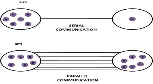
In serial communication, we can have only 1 bit transmitting at a time, while parallel communication the communication is much more efficient. However, timing in parallel communication means that all the bits must arrive at the destination at the same time. This is a major problem when communication is happening over long distances.
In our example above, the parallel line can send 6 times as many bits as the serial connection therefore it is theoretically faster. The reason as to why this is the case is due to the fact that parallel communication need clocking to synchronize the arrival time of the bits. The stream must wait until all bits arrive for a full byte to be transmitted.
Communication over serial connections requires fewer cables and wires as compared to that of parallel communications. These cables are also better insulated from noise and other forms of interference.
With parallel cables, the bundling can cause crosstalk and noise.
When using serial cables, the routers and other internetwork devices usually compensate for crosstalk before transmission of the bits. Therefore, the communication using serial cables is more efficient and can operate at higher frequencies.
Serial connection standards
In the previous chapter, we briefly discussed the various types of connectors used in the WAN. In the previously section we have seen that serial connections are less vulnerable to crosstalk, and since they require less wires, they are cheap to implement. This makes them ideal for WAN communications.
The different standards used in serial communications use one of three standards when connecting LANs to the WAN. These are described below.
-
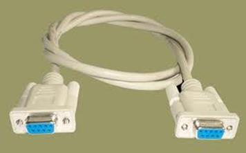
RS-232 – this standard uses either 9 pin or 25 pin connectors. They are used in serial connections for a variety of purposes and not just limited to WAN connections. Some of the ways they are used include; connection of PCs to printers, modems and other devices.
This is the port that we use to configure a router from the PC. The figure below shows the connector that is used.
- V.35 – this is the ITU standard for high speed serial communications. It combines the bandwidth of available on a couple of telephone circuits. This cable is used to connect the DTE devices to modems and similar digital line devices.
- High Speed Serial Interface (HSSI) – this standard supports speeds of up to 52Mbps, it can be used to connect LANs to WANs using high speed links such as the T3 lines.

TDM (Time Division Multiplexing)
Time division multiplexing is a technique employed in serial communications to split the bandwidth into slots so that simultaneous communication can happen between several devices. It was a technique first employed by Bell Laboratories to maximize the amount of voice traffic carried over a medium. Prior to the introduction of this technology, telephone calls required dedicated physical links from the source to the destination which was expensive to implement.
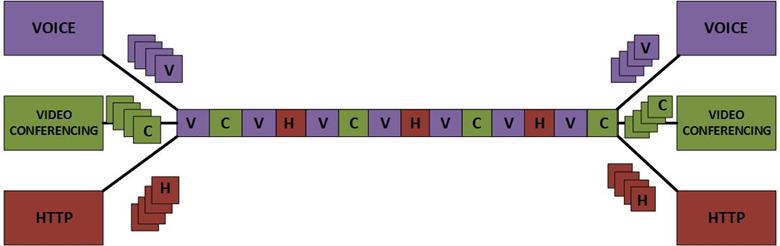
In the figure below, we have demonstrated TDM using three conversations over a network, web browsing denoted by “H” voice traffic denoted by “V” and video conferencing denoted by “C”. Notice that the medium is not only carrying one type of traffic, rather it is splitting the communication streams. The recipient rarely sees this happening since the communication is reassembled at the destination.
In serial transmissions, the use of TDM is used as a way to use the bandwidth more effectively. With this communication, the data is reassembled by the destination device.
When the source sends data, the data is split according to the type of protocol as shown above. The data is then transmitted in slots over the physical medium. When the data reaches the destination, the destination device reassembles the data into the specific protocols.
NOTE: in the above example, voice has been given first priority then video finally http data. This is typical in communication and it a principle under QOS (Quality Of Service) this will be discussed in more detail at the CCNP level and above.
DTE-DCE
The communication through the WAN is through the DTE and the DCE device. A serial link is usually made up of two DCE devices at each end. The DCEs connect to DTEs in the remote LAN networks.
The DTE is usually a router or similar device. This is usually the source of the information at a layer 2 perspective. The DTE usually sends the data to the DCE.
The DCE which in the scenario shown below is a CSU/DSU device, converts the data received from the DTE device into a form that can be transmitted over the WAN provider using the serial link. When the signal is received by the DCE at the remote network, it is converted to a form that can be used by the DTE which delivers the data to the destination device.
This is illustrated below.
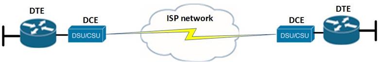
The DTE in networks is usually owned and maintained by the customer while the DCE devices are usually maintained by the WAN service provider.
NOTE: a CSU/DSU converts digital signals into a form that can be understood by the DTE, in analog signals, a modem is used as a CSU/DSU. In our labs, we do not use the CSU/DSU rather we simulate them using the V. 35. Serial connection with one male side as the DTE and the female side as the DCE.
WAN Encapsulation Protocols
In the WAN environment, we need to specify the particular protocol that the DTE should use. This is so as to make sure that the frames that are sent over the WAN link are correct. The choice of WAN protocol can be determined by a couple of factors.
Below, we have described the various WAN protocols that we will cover in this course.
- HDLC – on point-to-point networks, this is the default WAN protocol that is used by CISCO devices. It also defines some of the communication parameters used in PPP.
- PPP – is a protocols that connects many routers to the WAN, PPP is works at layer 2 and is independent of the Layer 3 protocol in use. This means that it can use IP, IPX and appletalk.
- Frame relay – is an industry standard switched data link protocol. It uses virtual circuits and it evolved from the X.25 protocol. It is more efficient and does not include options such as flow control and error control.
HDLC
This protocol is defined by ISO and it is therefore an open standard. HDLC uses synchronous serial transmission for error free communication between two devices.
HDLC is the default serial links layer 2 protocol and it is enabled by default. However, to configure HDLC on a router’s serial interface, the command: “encapsulation hdlc” is all that is needed.
To verify the encapsulation type on a CISCO router, the command needed is:

The output should show you the encapsulation type as shown in the output below highlighted in red.
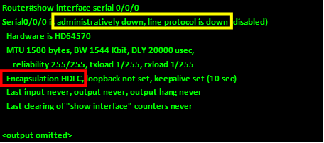
Troubleshooting serial interfaces
Troubleshooting a serial interface is a very important aspect in understanding WAN communication, in the output above – highlighted in yellow, the status of the physical layer and data link layer are shown. In the table below, the various messages for the physical layer status and data link layer status are shown and they describe what to look for in every message.
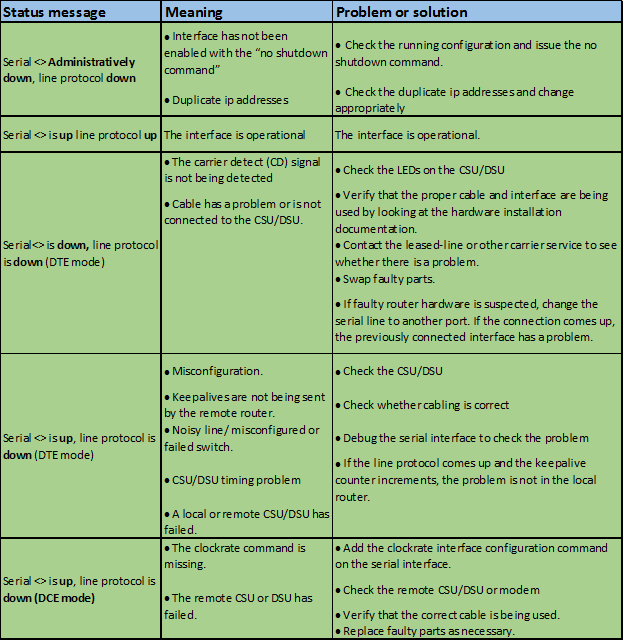
NOTE: these steps are very vital in passing the CCNA exams and are often asked, therefore it is imperative that you understand each message and the problems associated with it.
Summary
In this chapter, we have discussed serial interfaces in detail, we discussed how communication over serial links works as well as the types of serial links. We discussed the use of the DTE and DCE and then we looked at the default WAN encapsulation on CISCO routers which is HDLC. We finalized by learning how to troubleshoot serial interfaces. In the next chapter, we will look at the second serial connection protocol which is PPP (Point-to-Point Protocol).