


Overview
In this chapter, we will explore switching concepts and the basic configuration of a switch. We will discuss the switch’s operation, layer 2 and layer 3 switching as well as other concepts. We will conclude with the basic configuration of a switch and this will lead us into the discussion on VLANs.
CSMA/CD
We discussed the CSMA/CD in the chapter on Ethernet, we said that the LAN networks operate using several rules. In this type of communications, devices on the same Ethernet segment usually listen to the network media to determine if they can transmit or whether they have to wait. With hubs, only one device could transmit at a time, however, with switches, multiple devices can use the media at the same time.
Ethernet communication
In Ethernet communication, we have three types of ways in which messages are transmitted.
- Unicast
- Multicast
- Broadcast
Unicast
With unicast communication, a frame is usually sent from one node to a specific destination. In this mode, there is only one sender and one recipient. This means that the sender and the recipient as well as the switch in the middle must know about one another. In modern LANs, this is the most common form of communication especially on the internet using protocols such as HTTP, Telnet and others.
Multicast
In multicast communication, the sender usually transmits a frame to a group of nodes on the Ethernet segment. The type of protocol in use can typically determine whether multicast is used. In a teleconferencing call for example, a user may need to communicate with three other users simultaneously. In this case, multicast messages will be sent.
Broadcast
In case a user node needs certain information and it does not know who has the specific information, it may use broadcast type of communication. In this case, a frame is usually sent to all the devices on the same LAN. This communication is also useful if the message being communicated is meant for a large audience.
Addressing
In the Ethernet, the type of addressing used is the physical address which is typically the MAC address. This is the address that is used to communicate frames. When packets are received from the network layer, they are encapsulated into frames. This includes adding information such as the source and destination MAC address.
MAC address
As we have mentioned, the MAC address is the address that is used in the Ethernet. The address itself is made up of 48 bits which are represented in hexadecimal numbers.
When we were looking at layer 3 addressing, we said that IP address consist of two parts, the network and the host segment, similarly the MAC address is also broken up into two parts.
- the Organizational Unique Identifier (OUI)
- the vendor assigned number
The OUI consists of the first 24 bits of the MAC address. It is usually the code that has been assigned by the IEEE to a particular vendor. In CISCO switches for example, the OUI is usually: 0009.7C
The next 24 bits are usually a number that is assigned by the vendor for that particular device. It uniquely identifies the device hardware.
The entire MAC address is usually hard coded to the hardware of the switch and cannot change.
Duplex settings in Ethernet
On Ethernet networks, there are two modes of operation; the duplex determines whether the communication is unidirectional or bidirectional. The two duplex modes are:
- Half duplex
- Full duplex
Half duplex
In this type of communication, transmission of data is only one way, this means a device can either send or receive frames and not both. When HUBs were common in networks this was the communication that was used. This type of communication can be likened to using a walkie-talkie where you can either talk or listen but not both. While using the half duplex communication, the likelihood of collisions is high, therefore, CSCMA/CD is used to minimize them.
Full duplex
Full duplex communication provides for bidirectional flow of data. This means that devices using this type of mode, can send and receive frames at the same time. In modern switches, this is usually the default mode of operation. The chances for collisions are minimal.
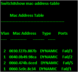
The mac address table
When we were discussing the operation of routers, we said that the forwarding decisions routers make are based on the information in the routing table. Similarly, the switches also have a database that contains addresses. This database is called the MAC-Address table and it is the basis by which switches forward frames.
When communicating, the switch uses this database to determine the source and destination of frames.
The steps taken when a switch wants to forward a frame are shown below.
- The frame is received by the switch from a port.
- The switch checks whether it has the source port from which it received the frame. If it does not it adds the source MAC address to its MAC address table.
- The switch then checks whether it has the destination port for the frame in its MAC address table, if it does not, it broadcasts the frame to all the ports except the port it received the frame on.
- When the destination node replies, the switch adds the MAC address to the MAC-address table and subsequent communication to this node will be unicast not broadcast.
The figure below shows an example of the mac-address table.
Configuring the switch
We have learnt of the IOS configuration modes as well as the basic configuration in a previous chapter. We saw the different modes as the user executive mode, the privileged executive mode, the global configuration mode and various specific configuration modes such as the interface configuration. In this section, we will configure some of the basic options in a switch which include:
- Hostnames
- Banners and passwords
- Management ip address
- Duplex settings
- Console lines and vty lines.
- Duplex settings
In the second part of this chapter, we will look at other switch concepts and configure other options as well as verify the switch’s operation.
The topology we will be using for this configuration is shown below.
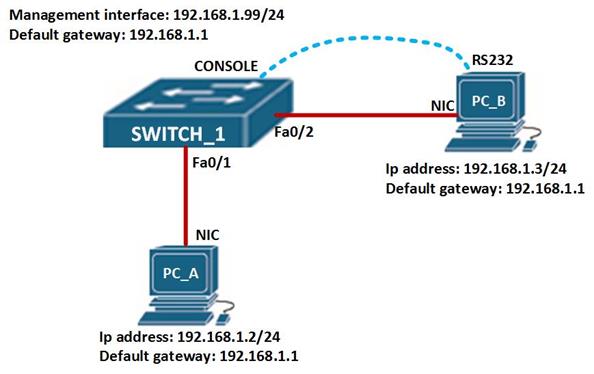
In this topology, we have 1 switch and 2 hosts. We will configure the switch using the console cable. Create this topology in packet tracer or a physical lab and follow the steps shown:
Hostnames, console & vty lines, banners and passwords
On more modern switches such as the CISCO 2960 switch which is the one we are using, the CISCO IOS is used, this is unlike older switches such as the catalyst switches. Therefore, most of the configuration commands we will use are similar to those used when we were configuring routers.
On SWITCH_1 command line interface, we need to enter the global configuration mode so as to configure most of the options. To access this, enter the following commands.
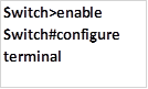
The first command gives access to the privileged access mode while the second, which is “configure terminal” will give us access to the global configuration mode.
In the global configuration mode we need to first change the hostname of the switch from “switch” to “SWITCH_1“. To do this, we enter the command: hostname <SWITCH_HOSTNAME>
In our scenario, this command is shown below.

When this command is executed, the prompt will change from “switch(config)#” to “SWITCH_1(config)#“.
Next we need to configure the line console and the 5 telnet line options such as the password, executive timeouts, and logging synchronous. The commands shown below are used to configure the passwords on both lines as “cisco” and the timeouts as 15minutes.
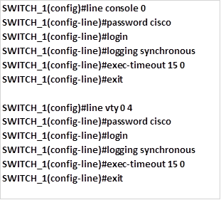
The command logging synchronous will prevent unnecessary messages from appearing on the screen while typing and thus disrupting the command while being typed.
The banner is a message displayed when someone tries to access the switch, with a message. We discussed some of the reasons that may make an administrator want to use a banner. In our case, we will use a banner MOTD which is configured using the command:

The pound symbol is used to indicate the beginning and end of the message. In our case we will use the message “WARNING. AUTHORIZED ACCESS ONLY!!!” which is configured using the command shown below on SWITCH_1.

When we were configuring routers, we noticed that to access the router remotely using the vty lines, we used an ip address. In switches, we need to configure an ip address, subnet mask and a default gateway much like a PC, the ip address is used to manage the switch.
By default, CISCO switches use VLAN 1 as the management VLAN, but it is advisable to change this since this can be a security vulnerability.
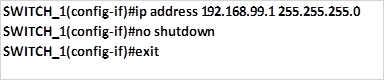
To enable management of the switch via a management interface, we need to create a management VLAN and assign it a management ip address. In our case we will use the VLAN 99 and issue it with an ip address of 192.168.99.1, this will allow the switch to be managed remotely via telnet lines.
We also need to configure default gateway so that traffic to remote networks can be accessed via the switch.
In our scenario, the default gateway will be 192.168.1.1
To configure the management interface, we follow the steps shown below.
NOTE: the “interface vlan command” is used to configure an SVI (switched virtual interface)
Step 1. Create the management VLAN interface, which is VLAN 99. Creation of VLANS will be discussed in more detail in the next chapter. However, the command we will use in this case is:

Step 2. Assign the interface with an ip address and subnet mask and activate and make it operational using the no shutdown command.
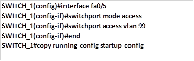
Step 3. On one of the switch interfaces, we need to link it to VLAN 99 management vlan, this is done as shown below. These concepts and commands will be discussed in part 2 of this chapter and also the chapter on VLANs.
To configure the ip default gateway so that traffic destined to remote networks can be forwarded we use the command “ip default-gateway <ip address>” command. In this scenario, the ip address we will use as the default gateway is 192.168.1.1 and this command is implemented as shown below.

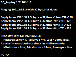
After this configuration, all the devices on the network should be able to communicate without any additional configuration.
As you can see from the statistics of PC_A below, pings to PC_B are successful.
Summary
In part 2 of this chapter, we will look at a few more concepts on switching and configure more options such as port security, we will also take a look at the various verification and troubleshooting commands that can be used on switches.