


Overview
in the previous chapter, we looked at the role of redundancy in the network and the prevention of loops in redundant LANs using STP. In this chapter, we will look at how we can utilize the links between our switches more effectively even in a network that STP has blocked links on. We will discuss what the ether channel is, the negotiation protocols used and then we will look at configuration, verification and troubleshooting of ether channels.
What is the Ether channel
As we have seen in this chapter, STP works by blocking links that are not necessary in order to avoid layer 2 loops, but picture the scenario shown below.
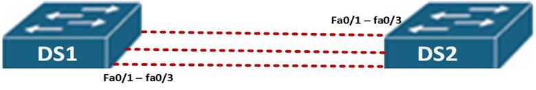
In this scenario, the two switches; DS1 and DS2 are interconnected by three fast Ethernet links for redundancy, this can be a major loop issue and as such, when STP is active on the switches, 2 of the links will be blocked and only one link will be in use.
This means that only 100Mbit will be in use whilst if all links were active, we would have 300Mbits in use which would be more effective use of the bandwidth between the switches.
Ether channel, is a way to use bandwidth on redundant links more effectively, by aggregating links and making them into a single logical connection as depicted below.
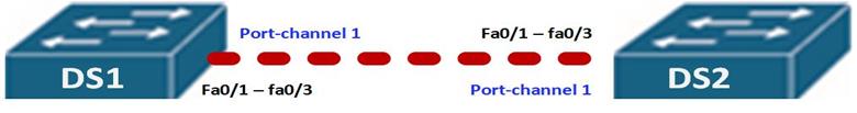
As you can see from our modified topology, the three fastEthernet Links have been bundled up into a single logical connection which is port-channel 1.
Benefits of ether channels
There are several benefits to using an ether channel in our switched networks
- By using the ether channel, we allow for load balancing since traffic will be directed across three links instead of one.
- In case of a failure in one of the physical links on the ether channel, the ether channel will still work with the remaining links – automatic failover, i.e. if fa0/1 in our scenario was down, the ether-channel would still use fa0/2 and fa0/3.
- The third advantage to using ether channels is that they simplify configuration of interfaces. This means that when an ether channel is implemented, we can configure it as we would any other interface, this would be simpler than configuring all three interfaces repetitively.
Negotiation protocols
There are two ether-channel negotiation protocols, as shown below.
PAGP – port aggregation protocol
- Developed by Cisco
- The port modes are defined as either auto or desirable
LACP – link aggregation control protocol
- Open standard as defined by IEEE 802.3ad standard
- The port modes are either passive or active. Passive is the equivalent of the PAGP auto and active is the equivalent of PAGP desirable mode.
In the CCNA curriculum, you will not be expected to configure an ether-channel for your exam, however, you are expected to understand the concepts behind it and it is a very useful concept in real world situations as well as in the CCNP level.
Configuring ether channel
We will configure ether-channel using the scenario shown below and see how it works as well as some verification and troubleshooting commands.

In the above scenario, we are supposed to configure ether channel on the links shown. i.e. fa0/1 – fa0/3, we will use PAGP in our configuration, however, LACP configuration options are similar.
The switches are using their default configuration, and the first thing we need to verify is the number of links that are active in the topology and whether STP is blocking redundant paths.
The output of “show spanning-tree active” on both switches shows that on DS2, fa0/2 and fa0/3 are alternate ports this means that they are blocked by STP as highlighted in red. All the ports on DS1 are active since this switch was elected the root bridge.
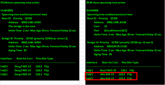
Successful configuration of the ether-channel will mean that the blocked paths will be transmitting data and will be root ports by the end of the configuration.
The first step is to enter the interface configuration mode for the three interfaces using the “interface range command” as shown below.
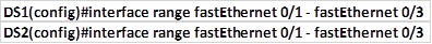
This will bring the interface range prompt which is denoted by “switch(config-if-range)#” as shown below.

In this mode, we can configure the ether-channel options, the two commands that we will use are:

NOTE: when the channel-protocol command is used and a negotiation protocol is enabled, the options on the channel-group command, will be limited to the options available for that protocol ONLY. I.e. if we use PAGP, the channel-group mode options we can use are “auto” and “desirable” ONLY, while for LACP, we can only use “Passive” and “active” options.
When the channel-protocol command is used, we cannot use the “ON” option in the channel-group modes.
When negotiating an aggregated link, the protocols will follow rules similar to those of negotiating trunk links as shown in the table below.
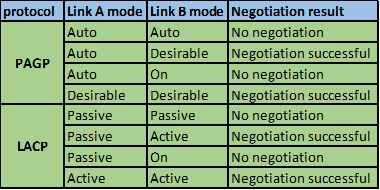
When we use the “ON” keyword on the channel-group command, we in effect activate the Ether channel exclusively, therefore if the other end of the link is in the other modes in either PAGP or LACP, the ether channel will not be active and the links will be down.
In our scenario, we will use PAGP and we will configure both sides as desirable mode.
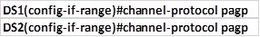
To enable the PAGP protocol we use the “channel-protocol” command as shown below for both switches.
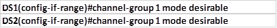
Next we need to configure the mode of operation as well as specify the logical port number for the ether channel. For this we use the command

In our case the logical number will be 1 and the mode will be desirable on both switches as shown below.
With this configuration, the ether channel should be up and the redundant links that were blocked by STP should now be active and we should only see the ether-channel port we have configured, and the output of the “show spanning-tree active” command on both switches should confirm this.
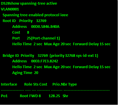
As you can see from the output of DS2 above, the new interface is port-channel 1, which is active and forwarding.
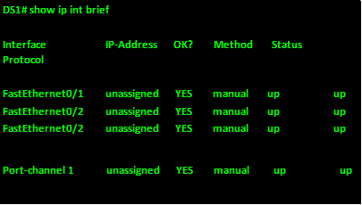
The show ip interface brief command should show us the new logical interface as well as its status as shown below.
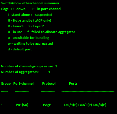
The last command that we can use to verify the status of an ether-channel, is the “show etherchannel summary” command and it will give information pertaining the configured ether-channels on the switch, the output of this command on DS2 is shown below.
With this, we come to the end of our chapter on the ETHER CHANNEL.
When using ether channels, we can effectively use the bandwidth on links that have been blocked by STP. However, take care when configuring ether channel since it may cause problems if not well implemented.
Summary
In this chapter, we have looked at the ether channel and how it can be used to open up links that have been blocked by STP so as to effectively use the available bandwidth. We looked at how it works, its advantages, the negotiation protocols used to implement ether channel as well as configuration and verification of PAGP. In the next chapter, we will look at inter-vlan routing and see how it fits in with the switching world.