


Overview
In the previous chapter, we looked at PPP, we discussed how PPP worked and we said that it works at the data link layer, in this chapter, we will look at the final WAN topic in this course which is frame relay. In part 1, we will discuss the concepts behind frame relay operation as well as the terminologies used we will then configure basic frame relay. In part two, we will look at more advanced frame relay concepts as well as troubleshooting commands.
Introduction to frame relay
Frame Relay is WAN protocol with high performance operating at layer 1 and layer 2 of the OSI model. In frame relay, costs are reduced by using less equipment, easy implementation and reduced complexity, despite this, it is possible for a customer to get high bandwidth, reliability and more resilience as compared to leased connections.
Frame Relay Operation
In frame relay, the connection from DTE to the DCE devices, is made up of both physical layer components as well as data link layer components.
In frame relay, the routers connected to remote networks are usually the DTE devices while the frame relay switch is usually the DCE device. The frame relay switches move data frames from the host networks across the WAN network to the remote DTE devices.
The diagram below shows how this works.
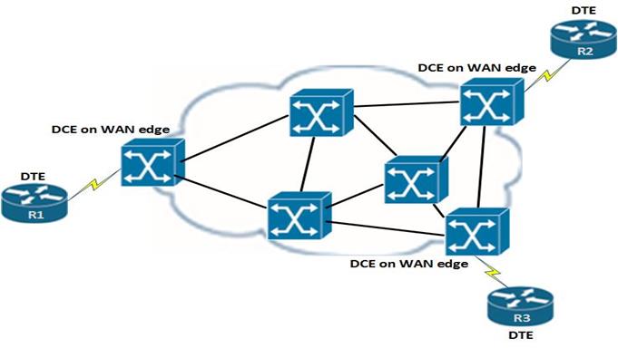
The DTE devices which are the routers, send data from the host network to the frame relay device which is the DCE device the DTE is connected to, then the frame relay switches which are the DCE devices, send the data to the DCE on the edge of the destination network, the data is then sent to the DTE devices on the destination network.
Virtual Circuits
In frame relay, the connection between the two remote DTE devices is known as a (VC) virtual circuit. Unlike direct connections such as PPP and HDLC, there is no physical connection between the host and destination networks between the frame relay networks.
The Virtual Circuits are used as a path for bidirectional communication between the source and destination devices. They are identified by addresses known as DLCIs which are usually given out by the WAN service provider.
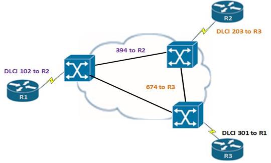
The DLCIs in frame relay are only significant in the host network or locally. This means that they are usually not unique in the frame relay network. They usually identify the virtual circuit to the equipment at the end of the frame relay circuit. This means that we can have devices connected by the same Virtual Circuit using different DLCI values.
In the figure below, you can see that R1 has a DLCI to R2 which is 102, however, this changes when it gets to the frame relay network. This is also the same for DLCI 203 on R2 to R3. This shows that DLCIs are only significant locally.
For data to be transmitted in a frame relay network, CISCO routers must know the DLCI value that is mapped to a network layer address towards the destination. The mapping of DLCIs to layer three addresses is accomplished either using static mapping or dynamic mapping.
Inverse ARP
Inverse ARP, is a protocol that resolves or obtains layer three addresses of routers in other networks from the layer two addresses – which are the DLCIs. the Virtual circuit can only be used if the layer 2 addresses are resolved to the layer 3 addresses.
Dynamic Mapping
Dynamic mapping of addresses in frame relay uses inverse ARP to figure out the network layer protocol address that is mapped to a local DLCI. A router in frame relay requests the layer 3 addresses by sending inverse ARP messages out of its PVC. When the frame relay switch responds, the router makes mappings of the DLCI values it gets to layer 3 addresses.
NOTE: inverse ARP is usually on by default on the physical interfaces on a CISCO router for all the layer 3 protocols that have been configured. This means that if you only use IP then the inverse ARP will only work for IP.
LMI Local Management Interface
The LMI is a mechanism that provides information on the status of a frame relay connection between a DTE and a DCE device. This means that it tells the DTE if the frame relay connection is still active by sending out messages every 10 seconds. If the frame relay switch does not respond, the connection is considered as down.
There are several LMI types, and they are incompatible with others, the LMI configured must match the LMI on the service provider. In this course, we will be using two LMI types which are:
- Cisco – Original LMI extension
- Ansi – Corresponding to the ANSI standard
Basic frame relay configuration
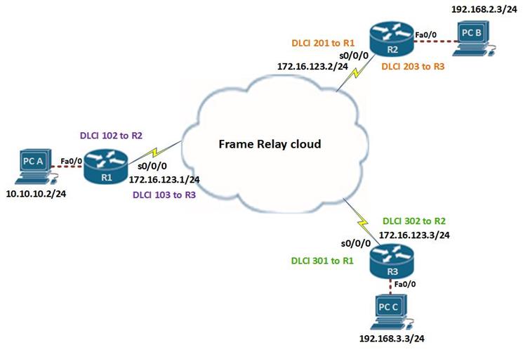
In this section, we are going to configure basic frame relay operation using the topology shown below. The configuration for the frame relay switch is not up to you and it has been done. Our tasks are shown below.
- Enable frame relay encapsulation
- Configure static and dynamic address maps
- Configure the LMI
The LAN interfaces on the routers have been configured with the first viable ip address on the subnet they are on, the serial interfaces have been configured with the ip addresses shown in the topology diagram above. The basic configuration on this lab has been done, and as such our task will be limited to the listed configuration items only. The success of this lab will be when the connectivity of the network is full and all the PC’s can ping each other. The routers have also been configured with EIGRP, therefore there will be layer 3 connectivity.
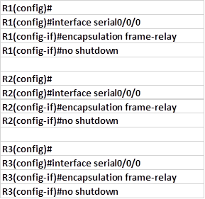
Step 1. Configure frame relay encapsulation on the serial interfaces.
The command needed to configure frame relay encapsulation on serial interfaces is:

On our three routers, we need to execute the command above and activate the interfaces using the “no shutdown” command as shown below.
NOTE: when configuring encapsulation, there are two options we can use either cisco or ietf, the default option on CISCO routers is “cisco”. If our network has routers from other brands, then we need to use the “ietf” encapsulation.
This will change the encapsulation from HDLC to frame relay, and this can be verified using the “show interface serial <interface_ID>” command as shown in the output below from R1.
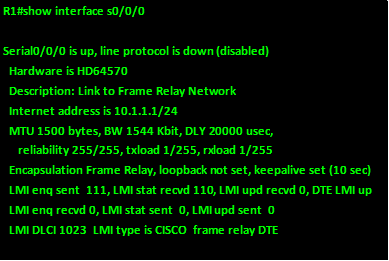
As you can see from the output, the interface is line protocol down, this means that it is not yet active.
Step 2. Bandwidth
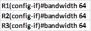
We can configure the bandwidth which will be used by the routing protocols such as EIGRP and OSPF when calculating the metric. To configure the bandwidth we use the command “bandwidth <number_in_kb/s>” in the interface configuration mode. The commands needed to set up bandwidth of 64kb/s on the serial interfaces on the three routers are shown below.
Step 3. LMI type
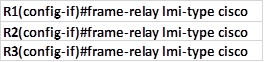
This is an optional configuration command and it specifies the LMI type to be used whether cisco or ansi. The command needed to accomplish this is shown below.

In our scenario we will use the cisco LMI type and it the configuration lines needed in the serial interfaces are shown below.
Step 4. Configure static frame relay maps
CISCO routers can use a variety of layer 3 protocols in frame relay. The task of the administrator is to configure the mapping for the layer 3 to layer 2 addresses used in frame relay. This means mapping a layer 3 address such as IP addresses to DLCIs. This can be done either dynamically or statically.
Static frame relay maps are usually configured manually on the router. The command needed to make the static mapping of a network layer address and a DLCI address is:

This means, to get to that ip address, use this DLCI on my router.
Frame Relay, is an NBMA network, this means that it doesn’t support multicast messages or broadcast messages. Therefore, in these networks, we cannot use routing protocols without additional configuration. The broadcast keyword used when configuring the frame relay maps is used for this.
When the “broadcast” keyword is used in the map, the packets that are needed to make routing possible are turned to unicast messages directed to each destination router in frame relay.
NOTE: routing will not occur if the broadcast keyword is missing in the frame relay map command.
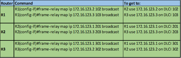
The topology diagram shows us the mapping addresses that will be used in this lab, and the table below shows the frame relay map commands that should be used in this lab.
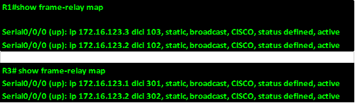
To verify the static frame relay mapping use the command: “show frame-relay map” on each of the routers as shown below for R1 and R3.
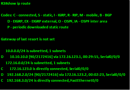
Testing connectivity on our hosts is the last thing we need to do in this lab, we can verify that all the three routers have the routes learnt via EIGRP as shown from the output of R3 below.
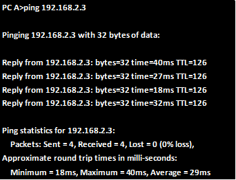
We can also verify connectivity by pinging from PC A to PC B and as you can see from the output below, the pings are successful.
This marks the end of the first lab, in the next section we will learn more advanced frame relay concepts and finish off with the troubleshooting section.
Summary
This is the end of part one of this chapter on frame relay. In part two, we will learn some more advanced concepts such as split horizon and subinterfaces in frame relay as well as learn the commands that can be used to troubleshoot frame relay.