


Overview
In part one of this chapter, we looked at the concepts behind frame relay operation. We discussed the role of the PVC’s, DLCI mapping, inverse ARP among other topics. In part two of this chapter, we will discuss more advanced frame relay concepts and finally look at the commands used to troubleshoot frame relay.
Advanced frame relay concepts
Split horizon
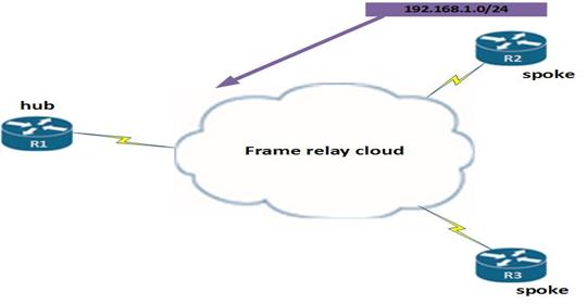
In NBMA networks, the topology used is mainly hub-and-spoke. This means that when we use routing protocols, we can have issues with reachability due to split horizon.
If you can recall, Split horizon prevents a router from advertising routes out the interface it learnt them from.
In the example shown below, R2 advertises the route 192.168.1.0/24, to R1. When R1 – the hub of the network receives this route, it has to advertise it to R3 so that the network can be converged, however, it cannot do this since there is only 1 interface and split horizon prevents it from advertising the route 192.168.1.0/24 to R3 out the same interface.
Subinterfaces
Recall we said that subinterfaces are virtual interfaces that are configured on a physical interfaces.
To avoid split horizon in frame relay, we can divide the physical interface using subinterfaces that connect to different subnets. With this, we can have two types of implementation; point-to-point, where 2 points use one network address, or point-to-multipoint, where more than 2 points use 1 subnet.
This would resolve the split horizon issue since the packets received on a physical interfaces are considered to be in a different interface which is the subinterface. This means that the same physical interface can then forward the packets out through another subinterfaces.
Frame Relay subinterfaces can be either point-to-point or multipoint mode:
Configuring subinterfaces
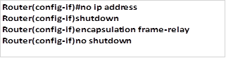
Step 1. to configure the subinterfaces, we first need to remove any layer three addresses that may have been configured physical interface. This is because the physical interface will be used by the subinterface and if it has a layer three address, the frames will not be received. To accomplish this, we can use the “no ip address” command in the interface configuration mode for the interface that is connected to the frame relay cloud.
Step 2. The configuration that is needed on the physical interface is the encapsulation command for frame relay as well as the activation of the interface using the “no shutdown” command. Step one and two are implemented as shown below.
Step 3. The third step is the most vital. We need to create subinterfaces for each of the Virtual Circuits in the frame relay cloud. The creation of the subinterface is done using the command shown below.
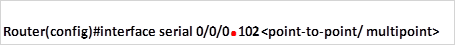
When configuring the subinterface, do not forget the period (.) between the interface ID and the subinterface ID. Which is our example above is shown in red.
NOTE: as good practice, when configuring subinterfaces, you are adviced to use a subinterface number that is the same as the DLCI number for that network. This makes it easier to troubleshoot when there is a problem.
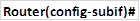
When this command is executed, the prompt will take us into the subinterface configuration mode which is denoted by the prompt shown below.
Step 4. The fourth task is to configure the layer three address that will be used for the particular network.
Step 5. The fifth and final task is to map the DLCIs to the specific subinterface. This is shown below.

with this configuration, we will be able to use routing without the problems associated with split horizon.
NOTE: the concepts in frame relay subinterfaces will be explored in more detail in more advanced courses such as CCNP, however, it is important to know these concepts since they are usually examined in the CCNA exams.
Other frame relay concepts
The final concepts that we will look at in this chapter are the payment options in frame relay networks. These concepts are vital in the real world where you may be required to review the service levels of the WAN.
Port speed – this is the speed at which the customer views the connection to the frame relay cloud. In most cases, this is the actual wire speed.
CIR (Committed Information Rate) – this is the actual speed of data transfer that the customer pays the WAN provider for over the frame relay link.
Bursting – in frame relay, if the network is not overloaded, the excess bandwidth is usually shared among the clients in the frame relay cloud without additional cost. This means that data can flow at speeds above the CIR.
Frame relay congestion – in frame relay, the routers can be notified of congestion. These mechanisms are meant to minimize the impact of a congested link. The two notifications that are sent are the:
- FECN – Forward Explicit Congestion Notification
- BECN – Backward Explicit Congestion Notification
When there is congestion in the network, the frame relay provider uses the following rules to frames that are sent to the frame relay cloud.
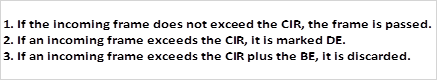
To view these statistics on the router, the command needed is:
Troubleshooting frame relay
There are several commands that can be used to troubleshoot frame relay. Most of these we have discussed when configuring frame relay. The commands listed below are key in troubleshooting and verifying frame relay operation.
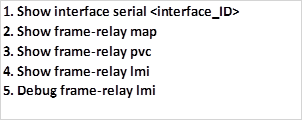
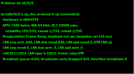
Show interface serial <interface_ID>
This command shows the operational status of the interface, the bandwith, the LMI type as well as the encapsulation that is in use, the output of this command on R1 is shown below.
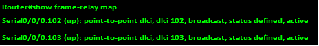
Show frame-relay map
This command shows the various frame relay maps whether dynamic or static, it can also be used to check the inverse arp processes on a router. The output of this command is shown in the example below.
If there are no mappings for frame relay, it is advisable to check the configuration made using the command “show running-config”
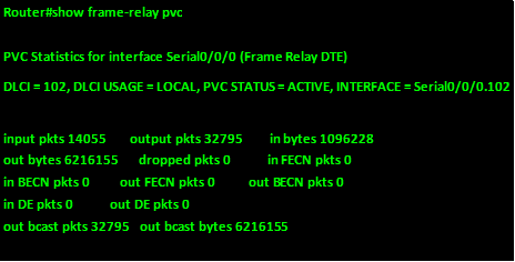
Show frame-relay pvc
As mentioned earlier, this command shows the status and statistics of the various PVCs on the router.
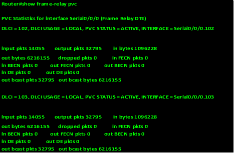
This command is also useful for viewing the number of BECN and FECN packets received by the router. The PVC status can be active, inactive, or deleted.
The “show frame-relay pvc” command displays the status of all the PVCs configured on the router. The output of this command is shown below.
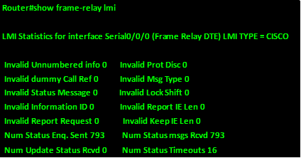
Show frame-relay lmi
The “show frame-relay lmi” command helps isolate the problem to a Frame Relay communications issue between the carrier’s switch and your router. Look for any non-zero “Invalid” items. The output of this command is shown below.
Debug frame-relay lmi
To find out if the router which is the DTE device and the frame relay switch which is the DCE are communicating properly through LMI packets, we can use the command “debug frame-relay lmi“. This is the last command that we will discuss in this chapter. The output of this command is shown below.
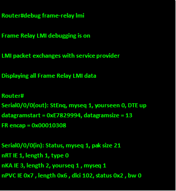
The meaning of the keywords in this output is shown below:
- “out” at the end of the interface denotes LMI status messages sent out of the s0/0/0 interface of this router.
- Messages that are received from the frame relay cloud are denoted by “in” at the end of the interface ID
- “type 0” denotes a full LMI status message
- “type 1” denotes an LMI exchange.
- “dlci 102, status 0x2” means that DLCI 102 is in active state.
The connection states made by a router as a result of inverse ARP requests are three. These are shown below.
- ACTIVE – full connectivity on the PVC, both the remote and local router are connected.
- INACTIVE – the connection to the frame relay switch is active, but the remote router is not connected to the frame relay cloud.
- DELETED – denotes that the router is configured with an invalid DLCI
The possible values of the status field are as follows:
- 0x0 – the DLCI has been configured but the PVC is unusable
- 0x2 – full connectivity
- 0x4 – the frame relay switch has not been configured with the specific DLCI; it has either been removed by the WAN provider or deleted on the DTE device
NOTE: the debug frame-relay lmi command can be very useful in troubleshooting a frame relay connection, however, debugging commands are usually resource intensive and thus they can affect the router’s performance. It is important to understand these verification and troubleshooting commands since they form a large part of question on WANs in the CCNA exams.
Summary
With the troubleshooting of frame relay section complete, we have come to the end of this chapter on frame relay, as well as the topics on WANs, in this chapter, we have looked at the frame-relay concepts, configuration and troubleshooting.
In the next chapter, we will discuss network security concepts.