


Overview
In the previous chapter, we learnt how NAT is important in helping devices in a network access the internet, we also looked at DHCP and how it helps in automatic ip configuration on hosts as well as the use of ACLs in filtering traffic in our networks. In this chapter, we will look at other ip services that you need to know as a CCNA. We will look at high availability using HSRP, VRRP and GLBP, NTP, SYSLOG, and finally we will look at CDP and how it can be used in a network.
High availability (HSRP, VRRP, GLBP)
Introduction
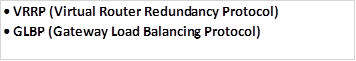
First hop redundancy protocols (FHRPs) will be the first ip service that we will discuss in this chapter. We will discuss and configure HSRP (Hot Standby Routing Protocol) which will help us learn about the two other FHRPs which are:
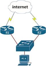
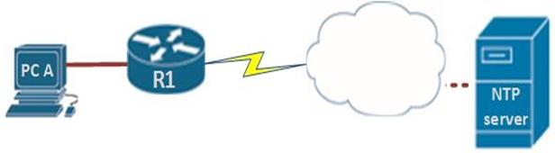
Picture the scenario shown below. In this network topology, PC A has been connected to the switch. There are two routers that access the internet. In this case, the PC has been configured with a default gateway that helps access the WAN which is the LAN interface on R1. The problem is, what if the interface on R1 goes down. Does this mean that this PC will not access the internet?
FHRPs are the solution to these problems. These protocols allow PC A to switch over to the other gateway when a gateway goes down. There are several questions that can be asked when it comes to redundancy as shown below.
- The speed at which this can happen
- How do clients respond to this
- Any ARP issues
The list shown below shows the characteristics of the three protocols.
HSRP
This was the first gateway redundancy protocol and it is cisco proprietary. HSRP has two timers; Hello timer which is usually sent out every 3 seconds and a hold timer 10 seconds
VRRP
This protocol was introduced in 1999 by the IETF, and it is the industry standard. VRRP has improved timers which are; 1 second for the hello timer and three seconds for the hold timer.
GLBP
In 2005, CISCO introduced GLBP, other than faster timers, it improved on HSRP by allowing load balancing across up to 4 gateway routers.
In the next section we will discuss and configure each of the three protocols using the topology we had as our example.
HSRP
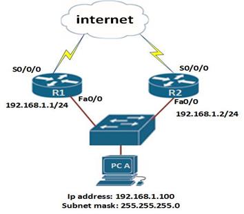
When using HSRP, the router’s interfaces in this scenario are configured with different ip addresses as shown in the diagram.
The HSRP configuration, involves putting the two gateways into a standby group, and once this is done; a Virtual IP address and MAC address can be created.
The virtual IP address and MAC address, is then assigned to the interface of PC A.
In this case, the virtual IP address and MAC address will be used by both routers, this means that if R1 is the active gateway, PC A will send data to the virtual ip address and then this will be forwarded by the router. However, if R1 goes down, the administrator does not have to change the configuration on PC A by changing its gateway, rather, the routers will change the active router from R1 to R2 and the virtual ip and MAC address will still be in use.
Configuring HSRP
In this section we will configure HSRP and verify whether redundancy will occur when a router goes down.
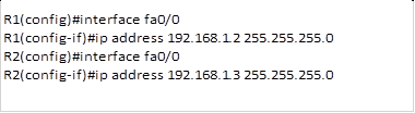
The first step we need to do is to assign ip addresses to the router’s fast Ethernet interfaces that are connected to the switch. This is done using the ip address command as shown below.
On the PC, we have used the ip address 192.168.1.100/24 with the default gateway as 192.168.1.1
NOTE: the default gateway is not active and therefore we cannot ping devices on remote networks.
The second step is to define the virtual router options.
Virtual router
A virtual router in an HSRP group has a virtual IP address and a virtual MAC address.
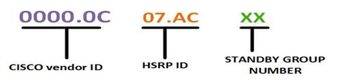
The HSRP MAC address has only one variable piece in it. The first 24 bits still identifythe vendor who manufactured the device (the organizationally unique identifier, or OUI).The next 16 bits in the address tell us that the MAC address is a well-known HSRP MAC address. Finally, the last 8 bits of the address are the hexadecimal representation of the HSRP group number.
The figure below shows this values:
0000.0c07.ac01
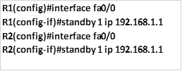
To configure HSRP, we use the command “standby” in the interface configuration mode. The command structure is shown below:

In this case, we will use the ip 192.168.1.1 as the gateway ip and this will be the one we will include in the standby configuration as shown below for R1 and R2.
These are all the commands that are needed to configure HSRP. To verify it, we will use the extended ping command on PC A as well as the various show commands on the two routers.
The extended ping command on a PC should show how many pings are missed when you disconnect one of the interfaces.
I.e. to verify HSRP operation using extended ping take the following steps.
1. Run the command “ping <ip address> -t” on a Windows™ PC, this will show ping statistics continuously.
2. Disconnect the interface on R1 that is connected to the switch.
3. Observe how many pings are missed between this time.
The command “show standby” can be used to verify the operation of HSRP, as you can see from the output below, this command will show the interface that has HSRP, the changes, the virtual ip address, as well as other statistics for HSRP.
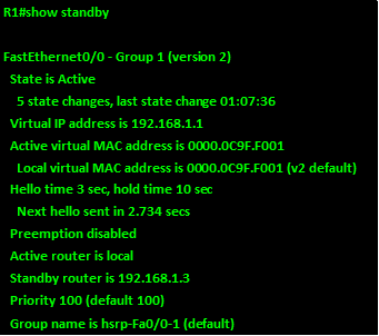
NOTE: there are many other commands that can be used to configure and modify HSRP however, these commands will be covered in CCNP level.
VRRP
VRRP (Virtual Router Redundancy protocol) was introduced by the IETF in 1999. It is the industry standard. The timers were improved to 1 second hello.
In this course we will not configure VRRP, since it is discussed in more detail in the CCNP level.
GLBP
Cisco designed a proprietary load-balancing protocol, Gateway Load Balancing Protocol
(GLBP), to allow automatic selection and simultaneous use of multiple available gateways,
As well as permit automatic failover between those gateways.
NOTE: Configuring GLBP is not in the scope of CCNA and it is covered extensively in CCNP, however, you need to understand how it works for real world situations and as such you are advised to read more on GLBP.
NTP
NTP (Network Time Protocol), is a protocol that synchronizes clocks of your network devices.
Correct network time within the network is important:
- Correct time allows the tracking of events in the network in the correct order.
- Clock synchronization is critical for the correct interpretation of events within the syslog data.
- Clock synchronization is critical for digital certificates.
To make sure all devices are synchronized with the same time information, we’ll configure our devices to receive the accurate time information from a centralized server.
NTP configuration
In CCNA, you are only expected to configure NTP in the client mode, to do this, we need to specify the location of the NTP server as shown below in our scenario.
There is only one command needed to configure NTP on the client. We need to specify the ip address of the NTP server using the command:
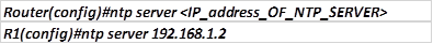
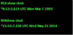
The show clock command on R1 before and after we configure this command is shown below.
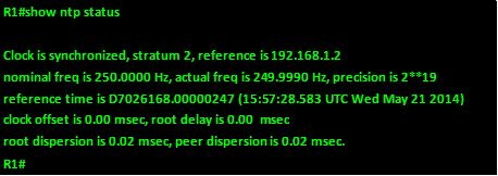
To verify that we are receiving the correct time, we use the command: show ntp status as shown below.
SYSLOG
You may have noticed that there are messages that appear in the CLI after execiting certain commands. An example is the output shown below.

This is the function of SYSLOG. SYSLOG allows you to view, save, search and even filter these messages which helps when troubleshooting.
The system message format can be broken down in this way:
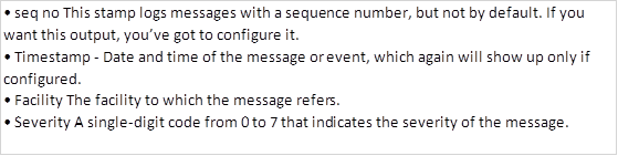
The severity of the message ranges from 0 to 7 and the table below shows the meaning of each number.
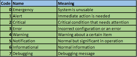
NOTE: the importance or severity decreases, i.e. 0 is the most severe while 7 is the least severe. You must understand these codes for not only your CCNA certification exams but also when troubleshooting in real world scenarios.
In this course, we will configure syslog option for traps.
This option will allow us to filter the logging information that is shown by syslog. This means that the level we configure is the highest level that will be shown.
To configure trap, we use the command “logging trap <severity>” in the global configuration mode. This is shown below.

In this example, when we configure the trap as error, we will only view error messages and more severe messages. i.e emergency, alert, critical and error messages only.
CDP
The final protocol we will look at is CDP.
CDP (Cisco Discovery Protocol) is a proprietary protocol that is enabled by default on CISCO devices and is used to discover other directly connected devices in the network.
With CDP, you can get information about hardware capabilities, interface and other information that is crucial in troubleshooting.
CDP works at layer 2 and therefore, the only thing needed for CDP to work is an enabled interface on a CISCO device.
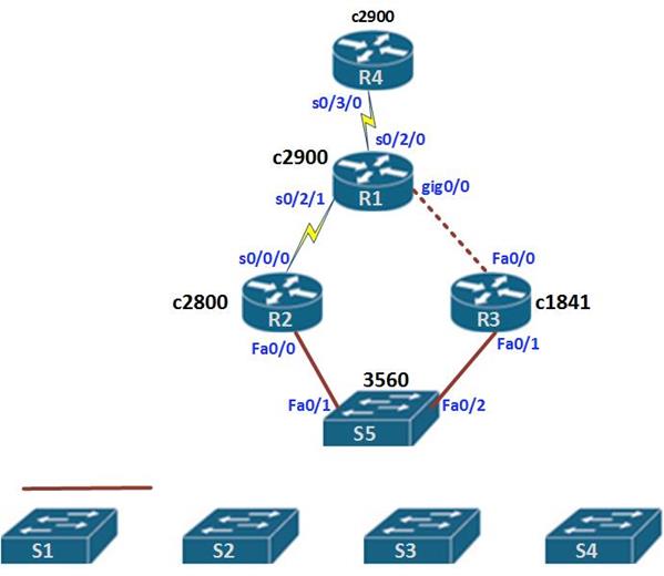
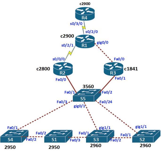
In the figure shown below, we will use CDP to identify the various devices in the network as well as their capabilities and ports. From this information, we will be able to draw the network topology.
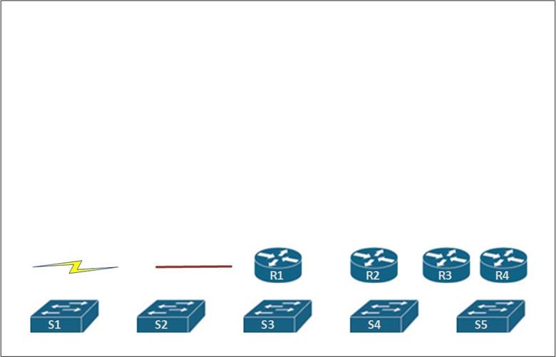
To demonstrate CDP effectively, we will mainly use the “show CDP neighbors” command. The output of this command will then help us to figure out the location and type of connection as well as the port number for each of the devices.
Show CDP neighbors
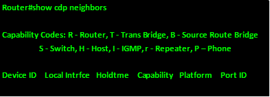
The show CDP neighbors command can be used to verify various things on a CISCO device. As shown in the output below, it can establish
- the device ID or the hostname of the connected device
- the local interface or the interface that this device is using
- the capability or the device type at the other end ; R is router and S is switch
- the platform, which is the version of the remote device
- The port ID which is the interface on the other end of the link.
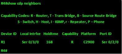
The first device we will check is R1. The show cdp command of this device is shown in the output below.
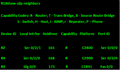
Based on this output, this is what we can gather:
- R1 is connected to R2 via a serial interface 0/2/2, R2 is a C2800 series router and it is using serial 0/0/0 to connect to this router
- R1 is connected to R4 via a serial interface 0/2/0, R4 is a C2900 series router and it is using serial 0/3/0 to connect to this router
- R1 is connected to R3 via a gigabit interface 0/0, R3 is a C1841 series router and it is using fast Ethernet 0/0 to connect to this router
Next we can view the output on R2
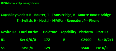
From this, we can tell that:
R1 is a C2900 router,
We also know that S5 connects to fa0/0 on this router and we know it is a 3560 switch.
The output on R3 shows the following.
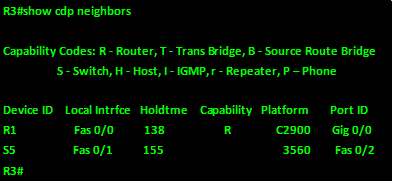
From this output, we know that this switch also connects to R1 and S5. To S5 using port fa0/1 and to R1 using port fa0/0.
Based on these commands, we now know the platforms for all the 4 routers as well as the ports they interconnect using this is shown in the table below.
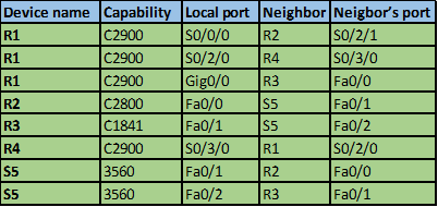
From this information we can begin visualizing the connections and draw them out. This is shown below.
We can now continue this process on the switches.
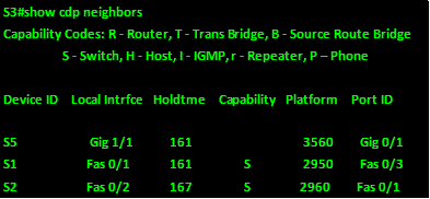
First we use this command on S5.
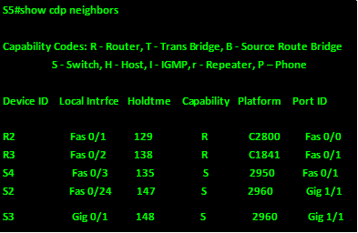
From the output, we can tell that:
- S5 is connected to R2 using fa0/1 to R2’s fa0/0
- S5 is connected to R3 using fa0/2 to R3’s fa0/
- S5 is connected to a 2950 switch (S4) on its fa0/3 interface and on S4 the interface connecting to S5 is fa0/1
- S5 is connected to a 2960 switch (S2) on its fa0/24 interface and on S2 the interface connecting to S5 is gig1/1
- S5 is connected to a 2960 switch (S3) on its gig0/1 interface and on S3 the interface connecting to S5 is gig1/1
We next view the output of show cdp neighbors on S1
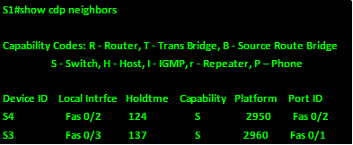
From this output, we can tell:
- S1 is connected to S4 via fa0/2 to S4’s fa0/2
- S1 is connected to S3 via fa0/3 to S3’s fa0/1
The output on S2 shows:
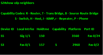
From this output, we can tell:
- S2 is connected to S5 via gig1/1 to S5’s fa0/24
- S2 is connected to S3 via fa0/1 to S3’s fa0/2
The output on S3 shows:
From this output, we can tell:
- S3 is connected to S5 via gig1/1 to S5’s gig0/1
- S3 is connected to S1 via fa0/1 to S1’s fa0/3
- S3 is connected to S2 via fa0/2 to S2’s fa0/1
The output on S4 shows:
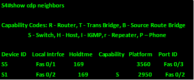
From this output, we can tell:
- S4 is connected to S5 via fa0/1 to S5’s fa0/3
- S5 is connected to S1 via fa0/2 to S1’s fa0/2
Now that we have the full picture, we know the following.
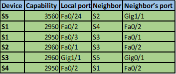
Based on this information we can now complete our topology as shown in the diagram below.
The lab we just finished shows how we can use CDP, to know about the devices that are directly connected on our networks.
REMEMBER: CDP is CISCO proprietary, and it is on by default. You only need to enable the interfaces using the “no shutdown command”
NOTE: CDP is a very important protocol, in the CCNA exams, you may be asked to determine the devices based on the output of this command, therefore be sure to understand how it works as well as how to interpret the show cdp neighbors command.
Summary
In this chapter, we have looked at other IP services and IOS protocols that we can use in our networks. We looked at first hop redundancy and discussed how HSRP, VRRP, and GLBP can be used to give our hosts gateway redundancy, we then looked at NTP and SYSLOG, finally we learnt how to use CDP to determine the various CISCO devices in our networks.
In the next chapter, we will look at IPv6.