


Overview
In the previous chapter, we looked at the role of the OSI transport layer in communication. In this chapter, we will look at the network layer. We will discuss the addressing used, the functions, and the different network layer protocols, introduce IPv4, understand how packets move in the network and finally give an overview in how we address the network using IPv4. You should be able to understand these concepts as they will be used in the chapter on addressing in IPv4 as well as in subsequent chapters.
Introduction
The network layer defines communication over the network through four basic processes which are addressing, routing, encapsulation and decapsulation. These concepts are vital in understanding routing.
Addressing
You may have sent a letter through the post office, while doing this, you are required to write the address of the recipient on the envelope and most likely your address for reply purposes.
In the same manner, the network layer is responsible for identifying the various devices in the network. However, unlike the postal addresses, addressing in the network layer is logical. This means that addresses are not fixed to the devices and they may change.
The addresses that are used in this layer are for remote delivery, if we use the post office analogy, remote delivery would be sending a letter to another organization. Local delivery – which will be discussed in a later chapter can be likened to sending a note to a colleague who is seated next to you.
Encapsulation
The network layer PDU- protocol Data Unit is the packet. Encapsulation entails adding layer 3 specific information based on the segments from the transport layer. Such information includes headers and trailers. It also divides the segments from the transport layer for remote delivery.
Routing
In the network layer, these are the services that direct the data from the host to the destination. In many scenarios, the packets might have to travel through many intermediary devices such as routers. Routing ensures that the path taken to the destination is the most efficient as defined by the administrator.
Decapsulation
When the packet arrives at the destination, it must be decoded and moved up the OSI layers to the application layer and thus the human network. The network layer carries packets and does not contain information about the upper levels such as the application type. Decapsulation is used to reassemble the packets to segments which are then used in the transport layer.
Network layer protocols
In the network layer, there are two main protocols that are used to carry data. These are:
- Internet Protocol version 4 (IPv4)
- Internet Protocol version 6 (IPv6)
There are other protocols that are used, however, they are beyond the scope of this course and will not be discussed.
IP (Internet Protocol) – Ipv4 and IPv6.
In most of this course we will look at IPv4, we will also discuss IPv6 briefly since the concepts in IPv6 are discussed in more detail in more advanced courses such as CCNP.
IP defines functions that are needed to transfer a packet from the source device to the destination device over the network. The network may consist of many nodes and for this reason the IP address does not change. IP does not track the various packets or manage their flow. These functions are performed at other layers. Some of IP’s characteristics include the following.
- Connectionless – this means that it is not necessary to have an established connection before packets can be sent.
- Media independent – regardless of the media; i.e. wireless, copper wire or fiber optic, the IP address does not change.
- Unreliable delivery (Best effort) – this means that the delivery of packets is not guaranteed, when packets are lost during transmission, they may be retransmitted depending on the protocols at other layers such as the transport layer. For example, if VOIP packets are lost they are not retransmitted since VOIP uses UDP, however, when HTTP packets are lost they have to be retransmitted since HTTP uses TCP.
Dividing Networks
One of the functions of the network layer is to address the hosts in the network. As the network grows, the network administrator, will need a way to manage these addresses. Take for example a country, can you imagine the chaos there would be while trying to send a letter, if all the addresses were not planned for? It would be a nightmare. Similarly, as the network grows the network administrator will need to work out a way to define different network segments.
It would be more manageable if the hosts in the network were divided into different network groups. These network groups are known as subnets.
The networks can be divided into different ways such as:
- Purpose
- Geographical scope
- Ownership
To divide networks according to these criteria please visit the link shown below for more guidelines.
http://www.cisco.com/c/en/us/td/docs/internetworking/design/guide/idg4/nd2002.html
So why divide the network?
As the network grows some of the Common issues that may be faced include:
- Performance degradation
- Security issues
- Address Management
To address these issues we need to subnet.
Dividing hosts into different subnets or networks can help improve performance.
Subnetting may help create security boundaries since not all the hosts in the network should communicate with each other. For example, the hosts in sales department may need to be separated from the hosts in the finance department.
The internet uses layer 3 addresses. If all the hosts connected to the internet were on one network, it would be almost impossible to communicate. As such, subnetting separates and makes networks more manageable when communicating on a large network such as the internet.
How networks are divided – hierarchical addressing
When we divide networks, we generally use a hierarchical addressing structure. A hierarchical address is important since each host can be identified. You can liken this to using a family tree to trace relatives.
When dividing a network, hierarchical addresses work similarly to addresses that you may use when sending a letter. Consider the diagram shown below.
|
South Korea, Seoul, 134- 00100. |
In this diagram, the address structure is hierarchical, the first level is the country that we are sending to, the second level is the city and the third level is the exact address of the recipient. Similarly, the logical addresses in the network layer contain a network portion and a host portion.
At the post office, the postman only needs to know the post office where the letter is to be sent to, which is similar to the code. When the letter gets to the post office, the post man there is responsible for delivering the letter to the intended recipient.
A layer 3 address also has a network and host portion. The routers in the network forward packets between the various separate networks by only looking at the destination network. When the packet arrives at the destination, the router will have to look at the whole address so as to deliver the packet to the intended destination.
When dividing large networks into smaller ones, we need to create other levels or layers of addressing. Just like the postal example we had above, when we use hierarchical addressing schemes, we can retain the higher level such as the country. We can then divide the country into various cities, and finally address the various hosts or users in the lowest level.
The IPv4 address is made up of 2 parts which are the network and the host portion. The address should have both parts for communication to be successful.
|
Network portion |
Host portion |
||
|
192 |
168 |
1 |
83 |
The IPv4 address is made up of 32 bits, we can divide these bits differently to either create more hosts addresses or more networks, however, in either case, the address has to be 32 bits long for the address to be complete.
Communication at layer 3
When a host wants to communicate with a host on a different network, an intermediary device such as a router has to be used. The router acts as a gateway to the other network as shown in the figure below.
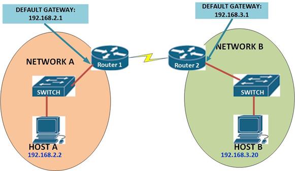
As you can see from the diagram above, there are two hosts on 2 different networks. In order to make communication between them possible, an intermediary device is needed between them, in this case a router. The router has the default gateway for the hosts and traffic from these hosts will pass through the routers. It is the job of the routers to determine where the packets belong.
Packets can only be forwarded when a route is present. All layer 3 devices must have a logical address so as to forward packets.
In our scenario above, the network connected to host B is a remote network from Host A, as such, we must have routes to this network from HOST A to HOST B. routers can forward packets based on routes that have either been statically configured or learned dynamically.
NOTE: we will discuss routing in upcoming chapters.
The router forward the packets using a routing table contained in its memory which contains information such as the Destination network, the metric and the next-hop device.
Summary
In this chapter, we have looked at the network layer. We have seen how communication is aided through logical addressing. We outlined the protocols in the network layer and discussed how networks are divided as well as how communication between hosts happens. In the next chapter, we will look at IPv4 addressing in depth and also discuss subnetting.