Overview
In the previous chapter, we looked at how we can segment a network using VLANs. In this chapter, we will discuss redundancy and how the end devices in the switched network are able to recover from a failure. We will discuss the role of STP in making sure that there are no loops as a result of redundant links in the network. In the second part, we will look at configuration of the various versions of STP and finally we will look at troubleshooting STP related issues.
All about redundancy
In earlier chapters on switching, we saw that the hierarchical network model is ideal in assignment of roles and functions in the network. We also saw that at the distribution and core layers of the network, redundancy can be achieved.
In the figure shown below, the access switches have redundant paths if the path on DS1 fails. Normally, users located on AS1 use the path shown in blue, however, if this path fails as shown by the red X, the frames would take the new path which is through DS2 as shown by the green arrow.
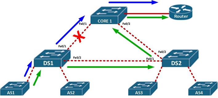
This is the essence of redundancy, to keep users connected even if there is a major failure on the network by taking an alternative path to the destination.
Layer 2 loops
In as much as redundancy is a good thing in hierarchical switched networks, there is a very high possibility of loops. Take the scenario shown below.

In this scenario, PC 1 wants to communicate with the node connected to DS2, the DS1 will receive the MAC address and the port for PC 1 and update its MAC table, it will then flood out this message out of all ports except the port it received the message on, which in this case is port fa0/1 and fa0/2. When DS2 receives the message, from fa0/1 first as shown by the purple arrow, it will update its MAC table with PC 1’s MAC and then broadcast the message out all ports except fa0/1 from which it received the message.
When DS 1 receives this message, it will “think” that PC 1 is directly connected to DS2 and thus it will update its MAC address table again.
The effect of this is that broadcast frames will go round the two switches, and since frames do not have the TTL field like packets, there will be a loop.
This can be a major disaster in a large network, and the loop may make the switch to behave like a HUB, since its MAC address table would eventually be filled up resulting in only broadcast traffic.
Broadcast Storms
The scenario shown above is a good example of a broadcast storm. It can be defined as a situation where there is so much broadcast traffic on a switch as a result of a layer 2 loop. This results in the consumption of all available bandwidth on the switch as eventually data cannot be forwarded by the switch.
Broadcast storms are caused by a loop in the network. A loop at layer 2 cannot be stopped since frames do not have a field that tells them that a frame has aged out. This is a major concern. We need backup paths in our LANs in case of failure and at the same time, we need to prevent loops.
Spanning Tree Protocol (STP)
Our networks need redundancy to protect the network in case a point fails, however, when redundancy is implemented, the likelihood of layer 2 loops increases. The spanning tree protocol, is a solution to the problem of loops in a switched network.
The Spanning Tree Protocol, works by blocking alternative paths to a networks and only allowing one path to be used. When the main path is disabled, STP reactivates the redundant paths and traffic continues to flow.
Consider the topology shown below:
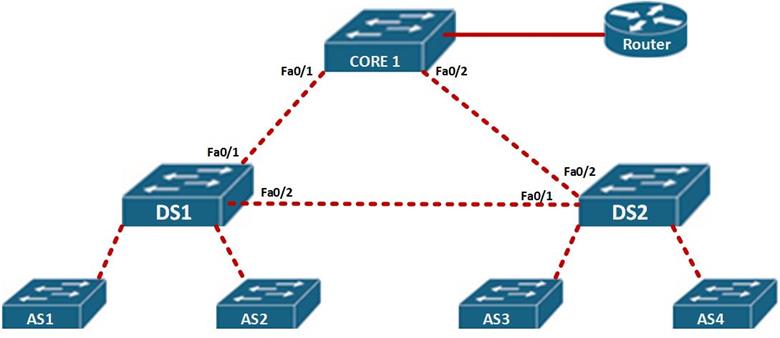
In this scenario, the path taken by AS1 and AS2, would be through fa0/1 to reach the router and fa0/2 to reach users connected to DS2. It would block the path between CORE 1 and DS2.
This would prevent a loop, if the link from DS 1 to Core 1 failed, STP on DS 1 would open up the blocked link – DS 2 to CORE 1, so as to recover from the erroneous link.
Spanning Tree Algorithm
The Spanning tree algorithm, is what STP uses to activate backup paths in the event of failure almost instantaneously. Similarly to algorithms used by routing protocols, the STA calculates the best paths in a LAN network and blocks alternative paths.
The root bridge
In a LAN network, Spanning Tree Algorithm elects a switch to be used as a central point in all the calculations, this is called the root bridge. This switch is ultimately responsible for the proper STP operation.
Root ports
The ports that are primarily used for forwarding frames in STP are the root ports. All the ports connecting to the root bridge on neighboring switches are root ports. When STP is fully converged, these ports will always be in forwarding state unless there is a failure.
Designated ports
The ports on the root bridges as well as one port on other links that are not directly connected to the root bridge are designated ports. In STP, these ports also forward frames.
Non – designated ports
When STP is fully converged, some ports will be blocked, these are the redundant ports. In STP, these ports are the non-designated ports and they can only become active in case of a failure.
In the topology shown below, all these ports are shown.
NOTE: there is always one designated port per link.
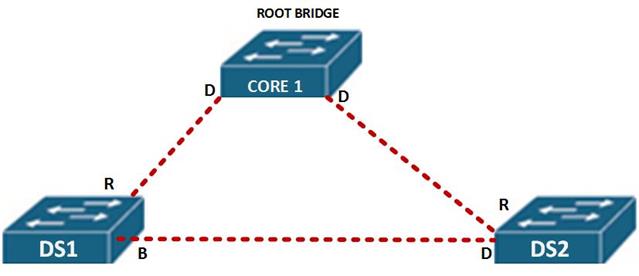
In this scenario, CORE 1, is the root bridge, therefore all its ports will be designated as shown by the letter D.
All the ports that lead to the root bridge, shown by R are root ports.
On the link between DS 1 and DS 2, there is one designated port and one blocked path. The blocked path is shown by B.
The reason that the port on DS 1 is blocked and not designated will be discussed later.
The root bridge
As mentioned before, the root bridge is the central point in STP and the main reference for calculations. The root bridge may be any switch on the network that wins an election process.
The root bridge election is determined by the BID (bridge ID). This field is made up of the switch’s MAC address and its priority.
After the election of the root bridge, the STA will choose the best paths based on the bandwidth on the links or the cost. The costs of different speed links is shown below.
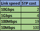
This field may be changed so as to influence the path that is made redundant.
NOTE: unlike in other protocols, where the higher the better when it comes to elections, e.g OSPF multi-access DR election, STP root bridge election prefers the lower values. Eg, lower mac address, lower priority, lower STP cost.
Election of the root bridge
In the previous section we said that the root bridge is used as the reference point for all STP calculation. The election of the root bridge is an important process and to understand STP, you must know it.
The BPDU (Bridge Protocol Data Unit) is a hello message, which is broadcast by the switches in the election process. The election process is illustrated using the topology below.
The BPDU, contains information shown below.
Root –ID: MAC address for the switch and its STP Priority
Bridge-ID: MAC address of the root bridge
Link cost – STP cost.
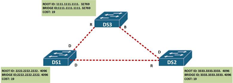
When the switches boot up, the BID and the ROOT ID is identical on each single switch in the network as shown below.

The switches then broadcast the BPDU frame with this information to the neighbors.
In our scenario, when the other switches receive the BPDU, they examine it against their own information to determine who the root bridge, in this scenario, when DS 2 and DS 3 receive this message from DS 1, they will identify DS 1 as the root bridge since it has a lower MAC address and priority of 4096.
When DS 1 receives this information, it will identify itself as the root bridge since it has the lower MAC address and priority.
The STA will now determine all the ports leading to DS 1 on the neighbors as root ports and all the ports on DS 1 as designated ports.
The next step is to determine which port is blocked between DS 2 and DS 3.
In this case, the STA algorithm will look at which port between these two switches offers the lower BPDU, in this case, the port on DS 2 will be chosen and therefore will be marked as the designated. The port on DS3 will be blocked. The port roles after election are shown below.
STP states and timers
The determination of the spanning tree is based on the information attained as a result of exchange of BPDU frames between the switches. When the spanning tree is being determined, the ports on the switches transition from various states and use three timers.
These port states determine the status of a port as discussed below.
- Blocking state – any non-designated port or root port, is considered a port in blocking state. This means that any port that is not forwarding frames. This port state means that the port will only receive the BPDU frames so as to ascertain the location of the root bridge as well as to know when there is a topology change.
- Listening – in this state, STP usually knows that this port can send and receive frames, the ports in this state can send and receive BPDU frames to inform neighboring switches that it can be an active port in STP.
- Learning- in this state, a port is usually preparing to forward frames, the switch which has its ports in this state is usually populating its MAC address table.
- Forwarding – when the port is actively sending and receiving frames in the network, it is usually in this state. This port can also send and receive BPDU frames to determine if there are any topological changes.
- Disabled – when a port is in shutdown mode due to the configuration of an administrator, this is the state it assumes.
We will see the port states as we proceed in this chapter.
In STP, there are three timers that are used. These determine the state of the switch or port in the STP topology.
- The Hello timer – by default transmitted every 2 seconds
- The Forward delay – by default 15 seconds before transitioning to forwarding
- Maximum age – by default 20 seconds
The hello timer is usually a message that determines if a link is still alive. The ports in the topology will receive a BPDU every 2 seconds. This is a keep-alive mechanism to determine if a port is still active in the STP topology. This value can be modified to a value ranging from 1 second to 10 seconds.
The forward delay is the duration that is spent by a switch in the listening state and the learning state, this value by default on CISCO switches is equivalent to 15 seconds for each state but an administrator can tune it to a value between 4 and 30 seconds.
The maximum length of time that a switch port can save the BPDU information is the max age time. This timer is usually 20 seconds but it can be changed to a value of between 6 and 40 seconds. When a switch port has not received BPDUs by the end of the maximum age, STP re-converges by finding an alternative path.
Portfast technology
On CISCO switches, some ports that may be connected to user nodes do not need to receive BPDUs and also need to transition immediately to the forwarding state. The CISCO portfast technology is a proprietary technology that allows such ports to transition immediately from blocking state to forwarding state.
STP convergence
To better understand STP, we need to understand the process a switch takes from boot-up to full convergence.
Step 1. Election of a root bridge.
Step 2. Election of the root ports.
Step 3. Elect designated and non-designated ports.
The election of the root bridge is through the sending of BPDUs, as we mentioned earlier, the switch with the lowest BID wins the election. The BID is made up of the SWITCH’s MAC address and the STP priority the switch that has the lowest BID wins the election and is made the root bridge.as we have mentioned earlier The root bridge is the reference or central point for all STA calculations.
The election of the root ports is the second step. The root ports as discussed earlier are the best paths to the root bridge. This is determined by the bandwidth available on each link.
The designated ports are non-root ports that can be used to forward traffic to the root bridge. There must be one designated port per link. All the ports on the root bridge are usually designated ports. Once they have been elected, STP chooses the links to block.
The ports that are blocked by STP are usually the ports that are not root ports or designated ports. These ports are marked as BLOCKED and will only be activated in case of a failure in one of the primary links.
STP process in action.
In this section, we will discuss this process by using the topology shown below, and finally we will determine Root Bridge and all the ports after convergence in STP using the information we have learnt thus far.
The topology shown below, shows the network topology which we will determine the STP ports and the root bridge for.
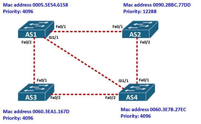
The first thing we need to determine is the root bridge. Based on the topology above, AS1 has a priority of 4096 and a mac address of 0005.5E54.6158, AS3 has a MAC address of 0060: 3EA1: 167D, while AS4 has a mac address and priority of 0060.3E7B.27EC, from this we can determine that the root ID of AS1 is lower since it has a lower MAC address, therefore it is the root bridge.
The other switches in this topology will add the Bridge ID value as the Root ID of AS1.
All the ports on AS1 will be designated while all ports on neighboring switches connected to AS1 will be root ports as shown in the diagram below.
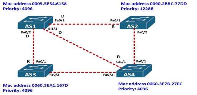
Next we need to determine which are the designated ports and the blocked ports on all the other remaining links.
From the topology above, the link between AS2 and AS4 is a FastEthernet link, however, the priority of fa0/2 on AS2 – 12288, is higher than that of fa0/1 on AS4 – 4096, therefore, fa0/2 on AS2 will be blocked and fa0/1 on AS4 will be designated.
The link between AS3 and AS4 is made up of FastEthernet links on both sides, however, the priority on both switches is the same, the tie breaker therefore will be the MAC address and in this case the MAC address of AS4 is lower. Therefore fa0/2 on AS3 will be blocked and fa0/2 on AS4 will be the designated ports. This is shown below.
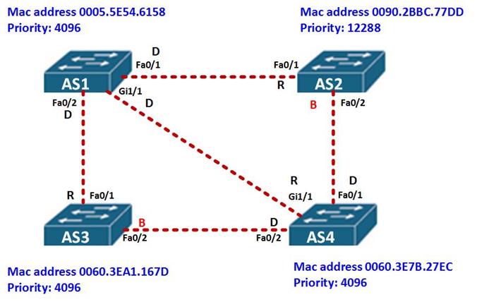
This completes the demonstration of the STP process on these switches.
Summary
In part 2 of this chapter, we will configure STP using the topology above, we will also incorporate the other concepts we have learnt in switching.

