


Overview
In part one of this chapter, we learnt how to configure VLANs on a switch. In this section, we will focus on deleting of VLANs on a switch, verification of configured VLANs as well as troubleshooting of some common VLAN problems.
Deleting VLANs
In other chapters, we have seen that using “no” at the beginning of a command is used to negate or delete configuration commands.
The configured VLANs unlike most of the commands in the IOS, are not stored in the startup configuration. If you issue the “show running-config” on switches, you will notice that the VLANs that were configured do not show up, this is because VLANs are not stored in the startup config rather, they are stored in a file known as: VLAN.dat.
To delete improperly configured VLANs, we use the command “no vlan <VLAN_ID>”, however, if we want to remove all the configured VLANs we issue the command “delete flash:vlan.dat ” in the privileged executive mode of a switch.
NOTE: you should be careful when using this command
Verify configuration of VLANs
To verify that the VLANs we had configured are in effect and operating in the proper ports, we use the command “show vlan brief” in the privileged exec mode on the switch. The output below shows the result of this command on SWITCH_A.
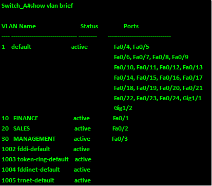
As you can see from the output above, there are eight VLANs on this switch. VLAN 1, 1003, 1004, and 1005 are usually on by default. VLANs 1003 – 1005 cannot be changed and they are reserved.
As you can see, the three VLANs we configured i.e VLAN 10 – FINANCE, VLAN 20- SALES and VLAN 30 MANAGEMENT, are all shown as active with the active ports indicated.
We can also use the command “show interface <interface_id> switchport”to verify the operational status as well as the configured VLAN on an interface. The use of this command on interface FastEthernet0/1 is shown in the output below.
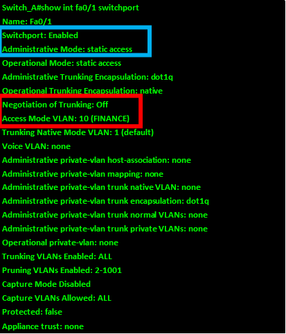
From the output above, highlighted in blue; the switchport mode is shown as static access. This means that this port has been configured to operate in the access mode. The configured VLAN is shown as VLAN 10, further this port cannot negotiate a trunk link since the first line in the red box shows “negotiation of trunking is off.
The command “show vlan < name> <vlan_name>” or “show vlan <id> <vlan_ID>”, will show the specific VLAN and the ports that are configured in this VLAN.
NOTE: when you use the “name” option, the “vlan_name” keyword is case sensitive, this means it has to be exactly as the name configured for the VLAN.
The output of the command show vlan name <VLAN_Name> for the MANAGEMENT vlan is shown below.
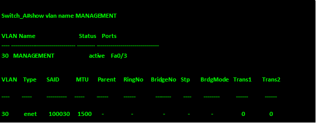
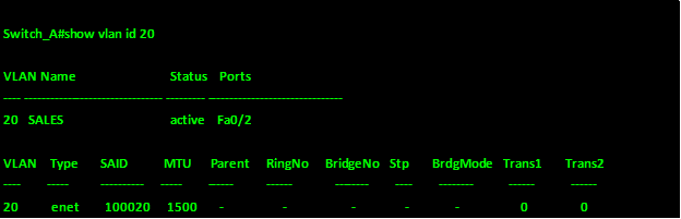
As you can see from the output above, the vlan management has only 1 port which is fa0/3. The output of the command “show vlan id <VLAN_ID>” for VLAN 20 is shown below.
There are other commands such as the “show interface vlan <vlan_ID>” which are not discussed since they are beyond the scope of this course.
Troubleshooting common VLAN and trunking problems
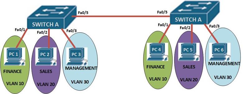
In this section, we will troubleshoot some of the most common VLAN and trunk problems. To do this, the switches shown below have been configured and we will troubleshoot the problems with VLANs using show commands, after which we will fix them.
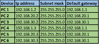
NOTE: to make this troubleshooting section more realistic, the configuration of the switches is not shown. Further, the end devices have been configured with correct ip addresses and default gateways as shown below, and to succeed in this lab, devices must be able to ping devices in their VLANs successfully.
The ip addressing for the end nodes is shown below.
Step 1: test connectivity
The first thing we will do is to test whether we can ping any of the nodes in the network. There are three VLANs with 2 PCs each, therefore we will ping each of the PCs in their respective VLANs to see whether there is connectivity.
The pings are:
PC 1 to PC 4
PC 2 to PC 5
PC 3 to PC 6.
All the fail, and from this we can deduce that there could be several problems.
- Interface shutdown
- Trunk misconfiguration
- Incorrect switchport mode or VLAN assignment.
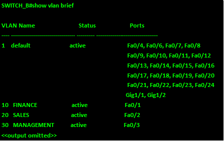
The “show VLAN brief” command on both switches should reveal which problem we are facing.
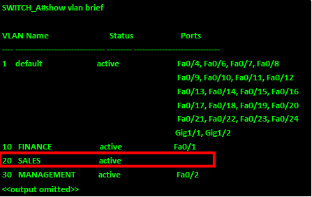
From the output of SWITCH_A above, we see that VLAN 20 has not been assigned port fa0/2, and VLAN 30 has been assigned port fa0/2 instead of port fa0/3. We therefore need to determine the operation modes of these ports and then fix the problems.
The “show interface <interface_ID> switchport” will show us the status of these ports.as shown below.
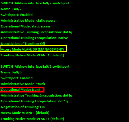
As you can see from the output of the “show interface fa0/2 switchport” and “show interface fa0/3 switchport” above, interface fa0/2 is configured to access VLAN 30 instead of 20 (highlighted in yellow) and interface fa0/3 is operating as a trunk instead of an access port (shown in red).
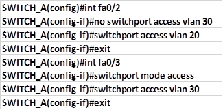
To fix this, we need to change the VLAN on fa0/2 from VLAN 30 to VLAN 20, we also need to change the operation mode of fa0/3 from trunk to access and assign it to VLAN 30. The commands shown below, are used to accomplish this.
This will fix the first problem. Attempting to ping is still not successful, therefore we need to check the trunk interface which in this case is fa0/5 on both switches to see whether there is any problem. To accomplish this, we issue the command: “show interface fa0/5 switchport” on both switches. The output is shown below.
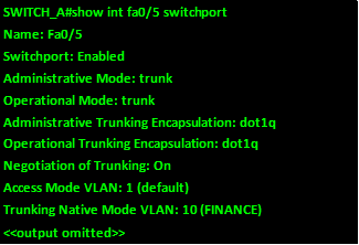
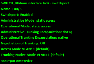
As you can see from the output above, interface fa0/5 on switch_A is a trunk however, the interface fa0/5 on switch_B is in access mode. So we need to change this and see if communication will be successful.
The command needed on fa0/5 on SWITCH_B is:
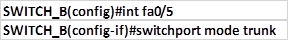
this will change the operation mode from access to trunk, however, we still can’t ping successfully from PC 1 to PC 4, but pings from PC 2 to PC 5 and PC 3 to PC 6 are successful. Further, there is a message on the buffer as shown below:
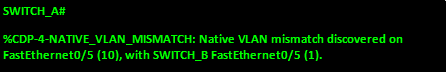
The native mismatch problem, happens when the trunk links are configured with different native trunks.
NOTE: the native VLAN on switches should always be the same on a LINK. And it should not be a VLAN that has hosts assigned to it.
In this case, the native VLAN should be VLAN 1 not VLAN 10 as it is on fa0/5 on SWITCH_A. to correct this problem, we issue the following commands.
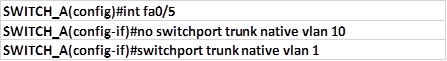
This should fix the error message and now there should be full connectivity between PC 1 and PC 4, PC 2 to PC 5 and PC 3 to PC 5.
Summary
The troubleshooting section of VLANs marks the end of this chapter, in this chapter, we’ve learnt about how we can segment broadcast domains on a switch using VLANs, effectively making smaller switches within the switch and each with its own subnet. We also configured VLANs and the trunk ports, we concluded by troubleshooting the various VLAN problems that may be encountered.
In the next chapter, we will look at the role of redundancy and loop prevention in our networks using STP.