


Overview
In the previous chapter, we looked at the various concepts that make switches work. In this chapter, we will look at VLANs. We will discuss what they are, how they work and advantages of using VLANs in our LAN networks. We will also configure VLANs in our LAN networks.
What are VLANs
VLANs (Virtual LAN) are a way to divide the switch into different LAN segments. As we discussed earlier, networks connected to a switch are usually one 1 broadcast domain, this means that all devices that are connected to a switch use 1 IP subnet by default.
VLANs are a way in which we can divide the switch into smaller broadcast domains and therefore make it possible to implement many subnets on one switch.
A VLAN therefore, is a way to create multiple logical switches on a physical switch. Each logical switch uses its own IP subnet.
Consider the scenario shown below.
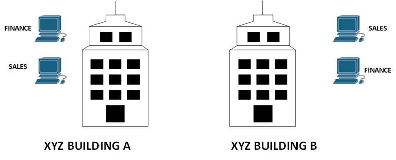
In this scenario, company XYZ has two departments; finance and sales. Each department has users located in both buildings at the same time each department is supposed to be on its own LAN segment, so as to separate the traffic between the FINANCE and SALES department. Typically, users on a switch are on 1 subnet which is a big problem. We therefore need a way to separate these departments which raises the question as to how to implement this solution. If a router is placed in between the buildings, we would require more than two Ethernet segments. And one switch would not be enough since these departments are on different subnets.
In this case, we can implement VLANs on a switch located between the two buildings. The users in each of the departments can then be assigned their own subnet.
This is one of the most significant uses of VLANs. As we continue with this chapter, we will elaborate on how VLANs are used in different scenarios depending on the challenges faced.
Why use VLANs.
The use of VLANs is very important in today’s networks. To appreciate VLANs, we need to consider why they are important.
- Security – when we use VLANs, we can use one physical device for users with different access rights, the traffic in a sensitive group can use the same switch as that of a group with common traffic without violating the security policies.
- Reduction of costs – by using VLANs, we can reduce the costs that would be needed if each department in an organization needed a physical switch. With a 24 port switch, and 20 users in different departments, we can implement VLANs to separate them without needing additional hardware.
- Performance improvement – as we mentioned earlier, the default operation of a switch is in one broadcast domain. This means that if a frame is destined to a node that is not on the mac-address table, the switch has to broadcast it to all the ports. This can be degrade the performance of a network. With the use of VLANs on the other hand, the broadcast traffic is limited to a particular VLAN.
- Administrative tasks improvement – the use of VLANs eases the work IT administrators have to perform to maintain the network. With VLANs, upgrading of the network, troubleshooting and other tasks are made easier. We will explore this in more detail as we progress.
Network without VLANS vs network with VLANs
In normal operation, when a switch receives a broadcast frame on one of its ports, it forwards the frame out all other ports on the switch. Take the scenario shown below.
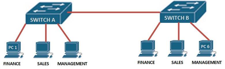
If PC 1 wants to send a message to PC 6 on switch B, the frame would be broadcast to all the users connected to switch A and switch B. however, if we had VLANs as shown in the scenario below, the frames would only be broadcast on their respective VLAN.
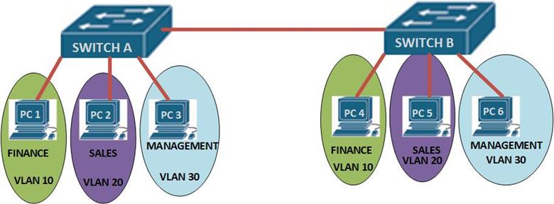
The interconnection between the two switches is a trunk link meaning that traffic from many VLANs can pass through it. In the above scenario, traffic on any VLAN is limited to that VLAN only. Meaning that PC 1 and PC 2 cannot communicate and PC 2 and PC 6 cannot communicate since they are on different VLANs, however, PC 2 and PC 5 can communicate since they are on the same VLAN.
NOTE: VLANs divide the switch into logical groups on different subnets. The interconnection between two switches is usually a TRUNK port.
Trunks
When using VLANs on several switches, the interconnection the switches is usually a trunk. If we use an analogy of a highway, the trunk line can be likened to a highway which interconnects many small roads. The trunk link allows traffic from many VLANs to move between the switches.
The two types of trunk links that can be configured on CISCO switches are the ISL trunk and the IEEE 802.1Q trunk ports.
There are several concepts that you should know when it comes to configuring trunk ports, these are:
- Native vlan
- Dynamic trunk protocol
Native vlan
This is the port that the switch uses to send untagged traffic. Tagged traffic is all traffic destined to a particular VLAN. Untagged traffic may be any traffic which is not destined to any particular VLAN such as control information.
Dynamic trunk protocol
DTP is a CISCO proprietary protocol that negotiates the trunking modes between switches. As we mentioned earlier, the port between the two switches A and B, is a trunk port, therefore it carries traffic from all VLANs across the two switches.
There are three modes in which ports on a cisco switch can operate:
- Access
- Trunk
- Dynamic
An access port is a port that connects to an end device such as a computer or an IP phone.
A trunk port carries tagged and untagged traffic across switches and sometimes to a router.
DTP works by negotiating the operation mode of a port on CISCO switches. If one side is configured as a trunk, then DTP can determine the mode of operation on the other end of the connection.
These concepts and more will be discussed as we continue with the configuration of VLANs.
Configuration
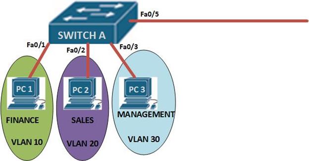
In this section, we will configure VLANs based. The topology below consists of one switch and 3 nodes. Our task is to configure VLANs on this switch while keeping in mind that we might need to add another switch.
We will not configure the PC’s since we will not be testing communication between the PC’s.
In this topology, we are expected to configure the following:
- Hostname of the switch
- Console and telnet lines passwords
- Switchports
- Switchport security
- VLANs
- VLAN names
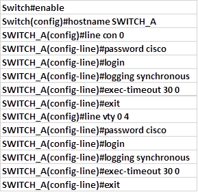
The first part which is the basic configuration is shown below.
Basic configuration
In the previous chapter, we learnt how to configure the switch’s basic operation. The commands shown below are a review of these concepts.
VLAN configuration
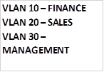
Part 2 is the configuration of the VLANs. In this scenario we have three VLANs i.e
To configure the VLANs go to the global configuration mode and type in the command:

the VLAN number is a unique number from 1 to 1005, however there are reserved VLANs which we will discuss later.
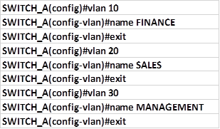
After executing this command, we will be taken into the VLAN configuration mode denoted by prompt:

in this mode we can name the VLAN as we have been instructed. In our scenario, the configuration commands needed to configure all the three VLANs are shown below.
Assign ports to the VLANs
Next we need to assign the ports on the switch to the VLANs we have configured. To do this we need to enter the interface configuration mode and follow the steps shown below.
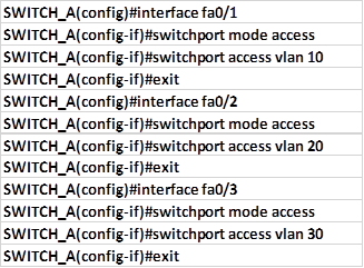
For PC 1 which is connected to fa0/1
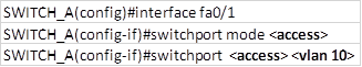
The command: switchport mode <access> specifies that this port is an access port and therefore it can only support traffic from 1 VLAN.
The second command: switchport <access> <vlan 10> specifies that the node connected to this port can only access VLAN 10, therefore the ip subnet for this port should be the same for all nodes on VLAN 10.
The commands needed to assign the switchports connected to the three PCs to their VLANs are shown below.
Configure port security
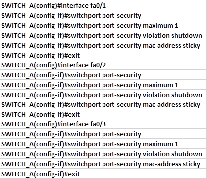
Now that we have assigned the ports to their respective VLANs, we need to configure port security for the three ports.
All three host ports, will use dynamically learnt mac-addresses, we will use a maximum of one MAC address per port, and configure the violation mode as shutdown. These commands are shown below.
Configure the trunk port
The last thing we will configure will be the trunk port which in our case is fa0/5
To configure this port as a trunk port the commands needed are:
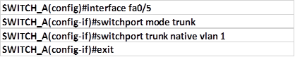
The command: switchport trunk native vlan 1, specifies that the native VLAN on this switch is VLAN 1.
NOTE: it is advisable to configure the native VLAN using an ID other than the default which is VLAN 1 for security purposes.
Summary
This is the last configuration command we use in this scenario. In part 2 of this chapter, we will learn how to verify VLANs operation, delete VLANs and troubleshoot common VLAN problems such as native VLAN mismatches.