Overview
In the last chapter, we discussed network security and saw its importance in our networks. In this chapter, we will delve into the world of ACLs, in part 1, we will look at the ACL concepts as well as configuring standard ACLs. In part 2 of this chapter, we will continue with configuration but we will focus on extended ACLs, other concepts, as well as troubleshooting ACLs.
Definition of an ACL
An ACL (Access Control List) is a list of statements that are meant to either permit or deny the movement of data from the network layer and above. They are used to filter traffic in our networks as required by the security policy.
The use of ACLs is crucial to network security and in this chapter, we will discuss how we can implement them so as to enhance network security.
Packet filtering
Filtering of packets, is a way to check the incoming packets and outgoing packets against set criteria so as to determine whether they should be forwarded or dropped. This is usually accomplished by a router.
In previous chapters, we said that routers forward packets based on the layer 3 information. When we apply filters, the router examines this information and decides whether the packet can traverse the network. If a packet passes the set criteria, it is forwarded, if not, it is dropped.
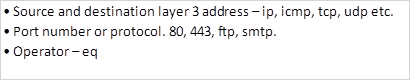
The criteria used by the router to determine whether packets can traverse the network is made by configuring ACLs. With access control lists, we can filter traffic based on; destination and source layer 3 address, destination and source port number, as well as the protocol in use.
ACL concepts
The ACL is usually a script that is executed in the router to check the packets based on the specified criteria.
The Access Control Lists configured on the router inspect packets against the rules that the administrator has set to determine whether the packet should be forwarded or dropped. The packets are inspected against the ACL criteria from the first to last configuration parameter in the ACL.
Below are some guidelines that may be useful in configuring ACLs.
ACL configuration guidelines
- ACLs should be ideally configured on the routers that act as firewalls in your network.
- ACLs should be configured on the routers in your network to control access to sensitive information in a particular subnet. For example, an ACL may be configured to allow authorized access to the finance department network.
- ACLs should be configured on the edge of your network, for example, to separate traffic from the Headquarters to other branches.
- ACLs should be configured to control traffic from the various protocols that you may have configured in your network. They may be used to filter traffic that is entering or leaving the router.
The three rules of configuring ACLs
There are three cardinal rules that should always be observed when configuring ACLs. These rules determine how traffic on a network will flow and therefore they should not be ignored.
- 1 ACL per protocol – this is to control each of the protocols that you may have configured on your router.
- 1 ACL per direction – there are two directions in this case; inbound traffic is the traffic that is coming into the router whilst outbound traffic is traffic that is leaving the router.
- 1 ACL per interface – this is meant to control traffic from leaving the router through a specified interface.
NOTE: these rules are crucial to understanding how ACLs work as well as configuring them in not only labs and the CCNA exams but also in real world situations.
What ACLs do
The ACLs work by doing the following:
- Blocking specified traffic so as to enhance the performance of the network
- Provide security by blocking packets destined to sensitive areas in your network
- Determining the type of traffic to forward based on the protocols
- Denying certain users access to the internet while allowing others.
As you will see in this chapter, the ACLs can be configured to perform a variety of functions that are critical to the security policies of the organization.
How ACLs work
The operation of ACLs is governed by rules that are set by the administrator. When the packets come into the router, the header is inspected for certain information that determines whether the traffic is forwarded or dropped. The routers only check the traffic that is sent through them and not traffic that is originated by the routers themselves.
There are two directions in which ACLs can be configured.
Inbound ACLs- with this type of ACL, the router checks the traffic that it receives from an interface against the configured ACLs before it can determine whether to route the traffic or not. This type of ACL is important since the router does not waste CPU cycles by processing packets that would eventually be dropped.
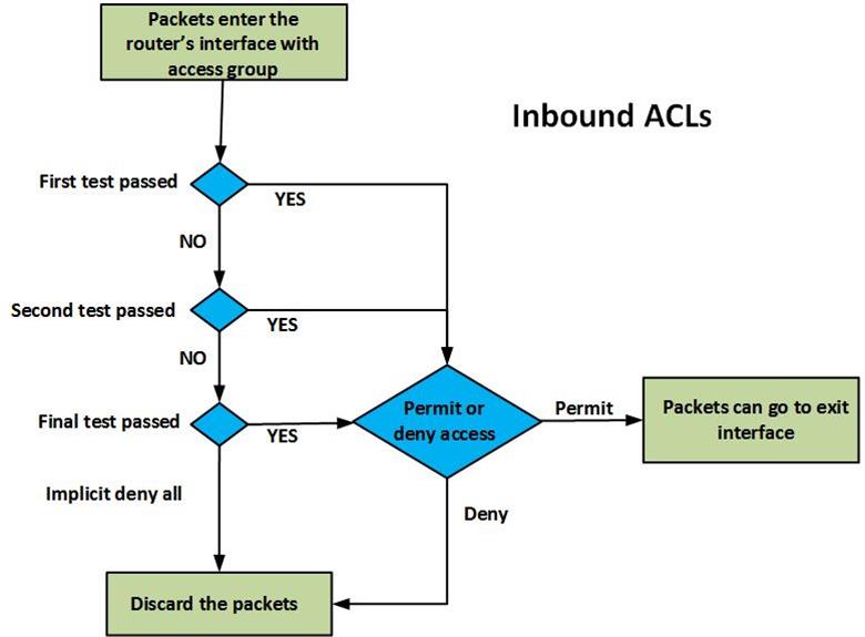
The figure above shows the operation of an inbound ACL. When packets are received on the router’s interface, they are inspected against the ACLs, the packet header is checked to see if it matches the set criteria, if it does not match any criteria, it is assumed that the router should not forward the packet and it is dropped. For every criteria, there is a decision that is made, whether to forward or deny access. Each packet that is permitted is allowed to be processed by the router and forwarded towards the outbound interface.
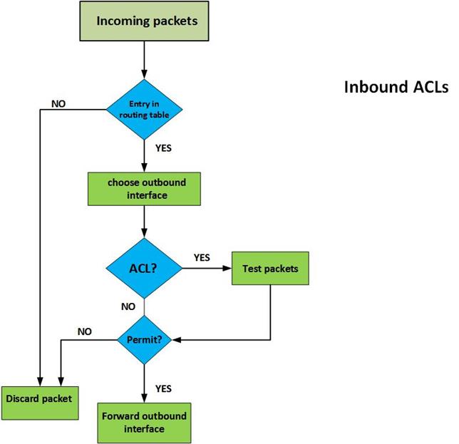
Outbound ACLs– with this type of ACL, the packets are usually processed and forwarded to the outward ACL for filtering. In this ACL, the router first checks in its routing table to see if the packet has a destination, if the destination is not in the routing table the packet is dropped. The second thing the router inspects is whether the outbound interface has an ACL, if the interface does not have an ACL for the packet, it is forwarded. Finally, for packets that have an ACL that is bound to the outbound interface, they are inspected by the ACL group statements to see if they match any criteria. If they match any criteria, the router decides whether to forward or drop the packet. If they do not match any criteria and the ACL does not permit them, they are dropped.
The figure shown below, demonstrates how this is done.
.
The implicit deny all statement
When configuring ACLs, it is important to note that at the end of the ACL, the router makes a decision. If the packet has been checked against all the ACL statements and it has not matched any criteria, the router will drop it. This is because the router assumes that the only traffic that should be allowed is traffic that matches one of the statements in the ACLs. To avoid filtering traffic that does not match any of the ACL statements, the command “permit any ” should be used to allow traffic that does not match any ACL but should traverse the router.
NOTE: these concepts are crucial to understanding configuration of ACLs.
Types of ACLs
There are several types of ACLs, however, in this course, we will focus on two types; standard ACLs and Extended ACLs.
Standard ACLs
With these types of ACL, an administrator can permit or deny packets based on their source IP address ONLY. These ACLs do not check the packets for any other criteria and therefore the destination is not usually checked.
Extended ACLs
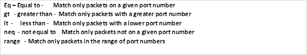
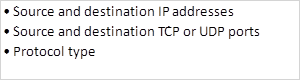
Extended Access Control Lists check the traffic against several criteria that has been set by the administrator. With these ACLs, you have more control over the traffic that you want to filter. Some of the criteria may include:
Where to apply ACLs
When configuring ACLs, we need to activate them by applying them on the appropriate interfaces. With this in mind, there are a few guidelines that can help to make the use of ACLs more effective.
For the extended type of ACLs, you should place them closest to the source of the traffic. Since they can filter traffic based on different types of criteria, it would be effective to place them on a router closest to the source of the traffic that is being filtered since this way other routers in the domain do not have to process undesired traffic.
Standard ACLs do not look at the destination address, therefore, you should place them closest to the destination network that you are filtering packets to. For example, if you want to filter traffic from network A to network B, standard ACLs should be as close as possible to network B.
When routers check packets against the configured ACLs, they do so in a sequential order. This means, from top to bottom, for this reason, when configuring ACLs, the ACL that matches the most should be placed at the top with the least used ACL at the end of the ACL group. In any ACL, there should be at least one permit statement or else all the traffic will be denied.
REMEMBER: the end of ACLs is usually an implicit deny all statement which means that if no traffic is matched against the ACLs, then it is automatically dropped.
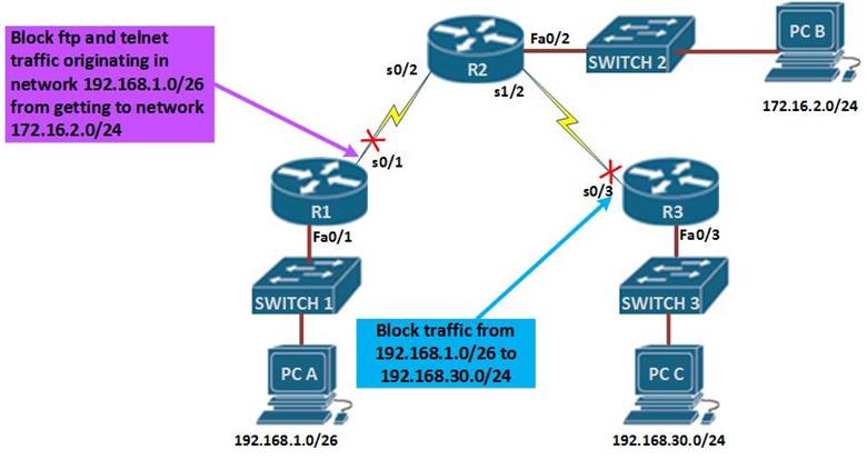
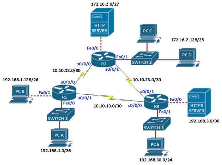
The figure above demonstrates how standard and extended access lists can be applied to control traffic.
In the network diagram, there are three LANs, network 192.168.1.0/26, network 192.168.30.0/24 and network 172.16.2.0/24, the network administrator has been asked to configure access lists based on several criteria.
The first scenario, dictates that standard access lists be used to block traffic from 192.168.1.0/26 from reaching network 192.168.30.0/24. In the rules we mentioned earlier, standard access lists should be close to the destination as possible, therefore, an access list on R1 would not be effective since blocking network 192.168.1.0/26 there would block access by hosts on R2 networks, therefore, the access list needs to be as close as possible to the destination network.
In this case, to block network 192.168.1.0/26 from reaching network 192.168.30.0/24, we would apply an access list on the inbound interface of R3 which is s0/3. This is shown in the figure by the red X on this interface.
Scenario 2 is slightly different, the network administrator only has control of the network 192.168.1.0/26 and he needs to deny FTP and TELNET traffic from reaching R2’s 172.16.2.0/24 network.
Using a standard access list would not work since it would block all the traffic, therefore, we need an extended access list which will block FTP and TELNET traffic from R1 from reaching R2’s LAN, all other traffic should be allowed.
Extended access lists are most effective near the source network therefore, the access list would be applied on the outbound interface of R1 and it should include the ports that should be blocked.
NOTE: the placement of ACLs is very crucial and it forms a major part of the CCNA exams especially in simulation scenarios, therefore, you should understand every aspect of this.
Configuring ACLs
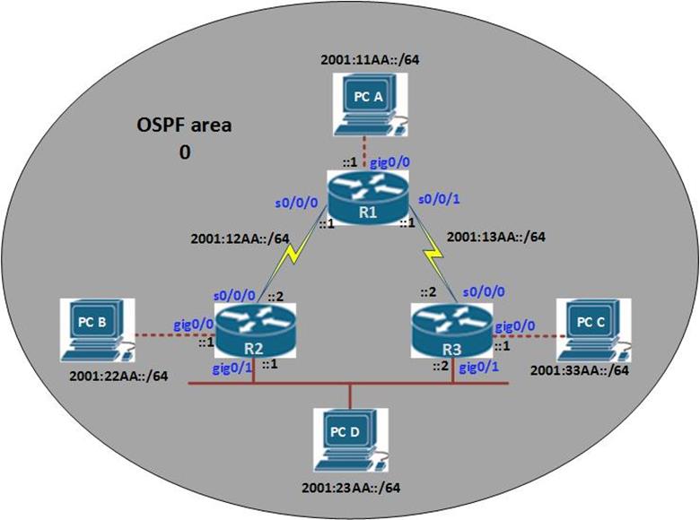
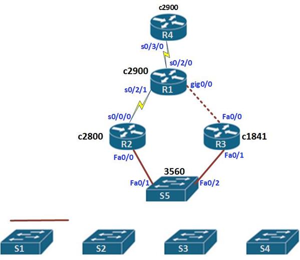
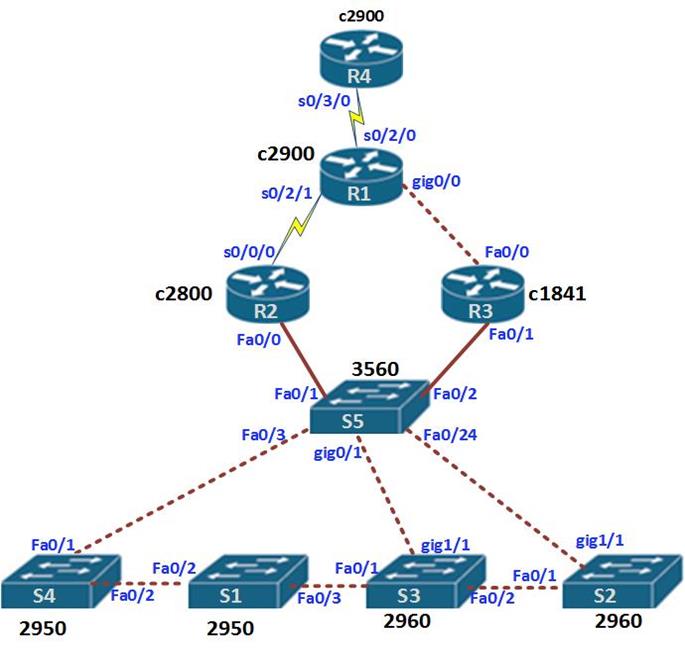
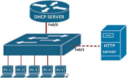
In this section, we will learn how to configure both standard and extended ACLs. The topology diagram shown below, shows the lab we will be using in our configuration. Part 1 of this section will focus on standard access lists and part 2 will focus on extended ACLs.
In the topology shown below, there are three routers and 6 LANs. The task is to configure ACLs according to the requirements and security policies in the organization.
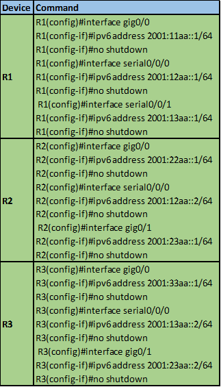
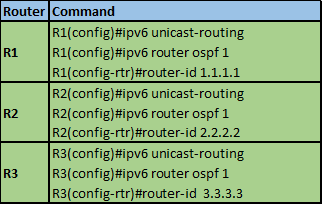
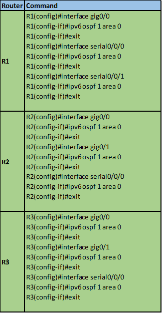
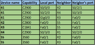
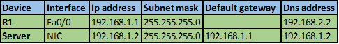
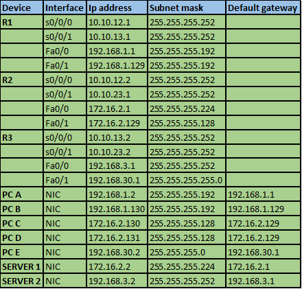
The IP addressing scheme is shown in the table below for all the devices in the network.
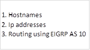
In this scenario, we are supposed to use both standard and extended ACLs. But first, we need to refresh other concepts that we have learnt in this course, therefore, the configuration items in this lab are:
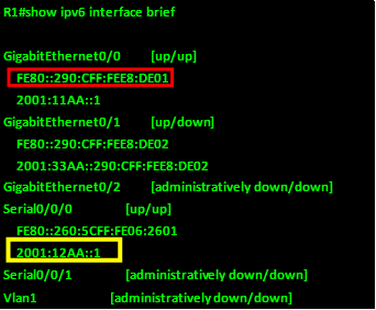
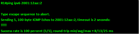
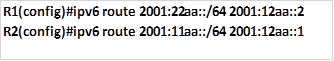
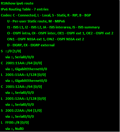
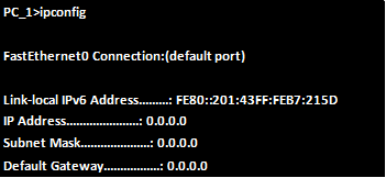
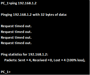
Ensure that all devices can communicate on the network before we proceed.
Standard ACL configuration.
The first scenario requires that we configure standard ACLs to limit traffic based on the following policies.
- Hosts on network 192.168.1.0/26 should not be able to access the HTTPS server located on network 192.168.3.0/30 but they can access all other networks.
- Only hosts on network 192.168.30.0/24 should be able to access network 172.16.2.128/25.
- Hosts on 192.168.1.128/26 should only be able to access the 192.168.1.0/26 network.
- PC D located on network 172.16.2.131/25 should not be able to access PC E.
Configuration commands
The “access-list global” configuration command defines a standard ACL with a number in the range of 1 to 99.
- The full syntax of the standard ACL command is as follows:

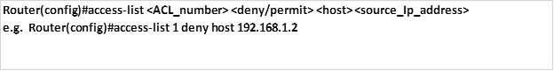
- The full syntax of the standard ACL command to filter a specific host is as follows:
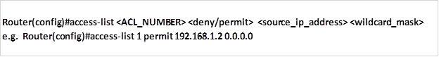
Or
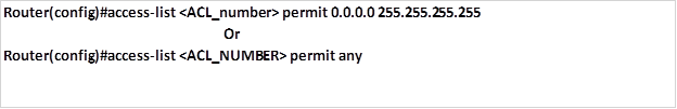
- The command to permit all addresses is:
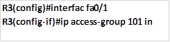
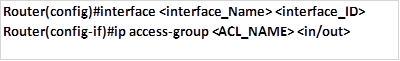
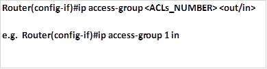
- The fourth command is used to apply the access lists to the appropriate interfaces.
As we mentioned earlier, there are two places we can apply ACLs, either inbound or outbound. This command is issued in the interface configuration mode as shown below.
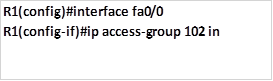
Task 1. Hosts on network 192.168.1.0/26 should not be able to access the HTTPS server located on network 192.168.3.0/30 but they can access all other networks.
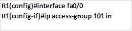
The standard ACL should block traffic from this network to 192.168.3.0 only, all other traffic should be allowed. Taking into consideration the rules of configuring ACLs, we will configure this ACL as close to the HTTPS server as possible, this means that the ACLs will be applied on the outbound interface to the HTTPS server which is fa0/0 on R3.
The first command will block the traffic from 192.168.1.0/26 from accessing the HTTPS server and it will be configured on R3, this is shown below.

The second command is supposed to allow all other networks to access this network, since applying this ACL without a permit access-list would block all traffic due to the implicit deny all.

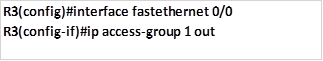
The third and final step on step 1, is to apply this access list to the outbound interface, which is Fa0/0 on R3 with the outwards direction as shown below.
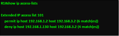
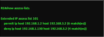
When this command is executed, traffic from network 192.168.1.0/26 will not be able to access the HTTPS server on 192.168.3.0/30 network but all other hosts in the network will be able to.
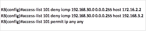
Task 2. Only hosts on network 192.168.30.0/24 should be able to access network 172.16.2.128/25.
The standard ACL should be able to allow traffic from 192.168.30.0/24 only to access the 172.16.2.128/25.
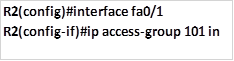
The only command needed is a permit ACL to allow the specified traffic to access 172.16.2.128/25 network, this should be configured on R2 and applied outbound to the fa0/1 interface. The implicit deny all will deny all other traffic from accessing this network. The commands needed to achieve this are shown below.
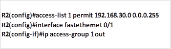
When these commands are executed, traffic from 192.168.30.0/24 will be allowed to access the 172.16.2.128/25 network, while all other traffic will be blocked.
Task 3. Hosts on 192.168.1.128/26 should only be able to access the 192.168.1.0/26 network.
This task means that traffic on the 192.168.1.128/26 network should be restricted to R1, this means blocking this traffic from going past this router.
We can use a deny statement to deny this traffic from accessing other networks as well as a permit statement for all other traffic. This ACLs can be applied to outbound serial interfaces on R1, only.
The commands needed to accomplish this are shown below:

Deny traffic from 192.168.1.128/25 from accessing networks beyond R1.

Permit all other traffic to networks beyond R1.
Apply the configuration to the serial interfaces on R1.
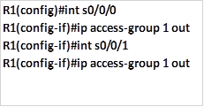
This will limit access of users on 192.168.1.128/25 to 192.168.1.0/26 only, users in the 192.168.1.0/26 network will be able to access networks that are beyond R1.
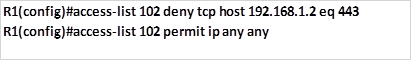
Task 4. PC D located on network 172.16.2.128/25 should not be able to access PC E .
This configuration is aimed at limiting access of only 1 host. To do this, we need to apply this access list on R3, we will block PC D with the ip address 172.16.2.131 from accessing PC A 192.168.30.2. in doing so, we should not break any configuration policy. i.e. we should follow the intentions of task 2.
To accomplish this, we will use the command to deny this host from accessing PC E while allowing PC C which will be executed on R3 using the commands shown below.

Deny PC D from accessing PC E

Allow all other hosts on network 172.16.2.128/25 to access network 192.168.30.0/24 while making sure that no policy is broken.
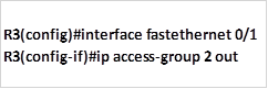
Applying the access list to the interface.
NOTE: to be effective at configuring ACLs, you should make it a habit to write down the commands that will be used in a sequential order on a program such as notepad before executing them on the routers. This is to ensure that the commands you have used are correct.
The use of the wildcard mask is essential in ACLs and a MUST. If you have forgotten this concepts, review the chapters that discuss the use of wildcard masks.
Summary
In part 1 on ACLs, we have discussed the role of ACLs in the network. We learnt what they are as well as how they used. We finished off part 1 with configuration of standard ACLs. In the part 2, we will look at Extended ACLs, other ACL concepts and finally we will finish off with configuration of extended ACLs and troubleshooting of ACLs.